
Yating Yuan, Bingqian Zeng, Tongning Hu, Xiaofei Li, Kuanjun Fan. Design and analysis of a tunable coupler for application to adjustable beam injectors[J]. High Power Laser and Particle Beams, 2022, 34(4): 044006
- High Power Laser and Particle Beams
- Vol. 34, Issue 4, 044006 (2022)
Abstract
The RF electron gun and the RF linac[
(1) Avoiding the secondary correction for the mismatching coupling factor induced by machining and construction errors.
(2) Keeping a small coupling hole under the condition of heavy beam-loading, then induced field asymmetry can be reduced.
(3) Making the coupler more flexible for the applications with different beam current, and critical-coupled states can always be achieved to avoid high backward power.
(4) Making the acceleration system more compact without high-power attenuators installed on related RF power transmission waveguides.
Present researches show that the adjustable coupling factor can be realized by adjusting depth of cylindrical regulators Te and Tm which are inserted in the electrical field and magnetic field region of ridge waveguide coupler respectively[
In addition, due to the machining installation errors, the resonant frequency of the actual cavity deviates from the design value. Thus, another tuning rod in the radial direction of the cavity or squeezing adjustment hole[
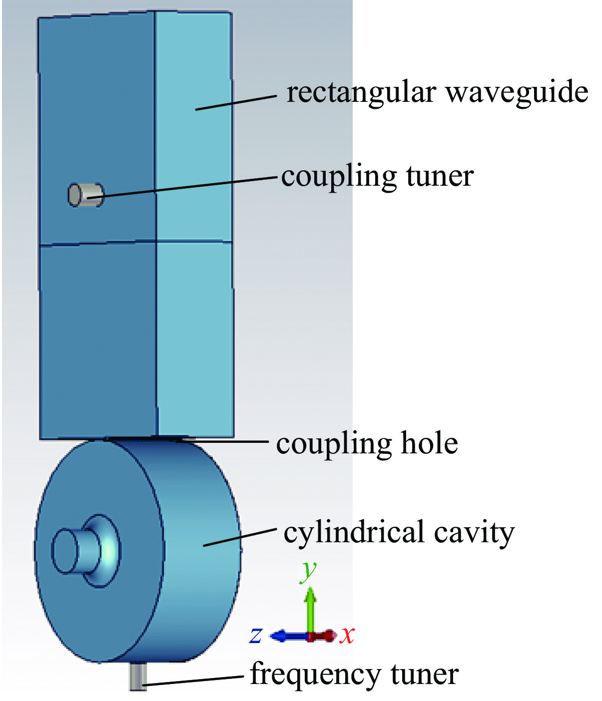
All of the above methods are individual adjustments for the coupling factor or the resonant frequency. In this paper, we take a standard standing-wave (SW) cavity with a rectangular waveguide coupler as an example, in which a coupling tuner (Tc) is inserted into the contraction waveguide, and a frequency tuner (Tf) is inserted into the cavity in the opposite direction of the coupling hole, As shown in Fig.1. Firstly, we construct a theoretical tuning model in manner of electrical circuit for such coupling system and analyze it in depth. Secondly, we conduct a 3D electromagnetic simulation to design corresponding structures and verify optimal insertion position for Tc. At last, the joint adjustment of Tc and Tf are performed to obtain the tuning range for the coupling factor and keep resonance frequency stable in the meantime. Therefore, the adjustments of coupling factor and resonant frequency can be achieved simultaneously, which make the coupling factor flexible with the beam intensity while maintaining the cavity resonance frequency stable at the design value. The design results and involved research method can be extended to all RF accelerating structures.
![]()
Figure 1.Simulation model of the coupling system
1 Online tuning methods for the waveguide coupler
1.1 Coupling tuning theory
The microwave equivalent circuit method is used to theoretically analyze the power coupling system between the power source, waveguide coupler and cavity.
When viewed from a plane of detuned short in the input waveguide, a cavity can be equivalent with an R-L-C shunt circuit as illustrated in Fig.2(a), whose resonant frequency is expressed as the following,
![]()
Figure 2.(a) Equivalent circuit of a one-port-coupled cavity and (b) equivalent circuit of a coupling tuner Tc inserted into the waveguide
As shown in Fig.2(a), the equivalent circuit includes a matching power source, an input waveguide with characteristic impedance 1/Ge, a coupling hole and an SW cavity. The coupling hole between the cavity and the waveguide can be equivalent to an ideal transformer whose turn-ratio is n. There is a certain conversion relationship between n and the coupling factor β. In the equivalent circuit, assuming that the end of the input waveguide is a detuned short plane, on which the accelerating cavity can be regarded as a parallel R-L-C equivalent circuit[
where β0 and ω0 are the initial coupling factor and the resonant frequency of the cavity, respectively. ω is the frequency of the RF power source, and Q0 is the intrinsic quality factor of the cavity. It can be seen that in the case where the parameters of the RF power source and the cavity are well designed, the normalized admittance of the RF cavity mapped to the source is only related to the resonant frequency of the cavity ω0. A rod (Tc) with axis parallel to the electric field in the waveguide can be treated as an equivalent circuit branch as illustrated in Fig.2(b). The normalized admittance induced by the post changes with the insert depth h, and the variation can be described by the following expression,
where
The equivalent circuit of the system with Tc is displayed in Fig.2(a), the total input admittance at the insertion plane can be demonstrated by,
where Kg is the wave number, l is the distance between the insertion plane of Tc and the plane of detuned short.
As shown in Fig.3, the normalized admittance seen from the plane of B-Bʹ can be expressed as a function of b, which is related to the coupling rod Tc.
![]()
Figure 3.Equivalent circuit of a tuning system
where
1.2 Resonant frequency tuning
The cylindrical cavity working at TM010 mode[
Inserting a tuning rod (Tf) in the symmetry direction of the coupler on the cavity, then the frequency can be tuned by adjusting the insertion depth of Tf, which can be explained by the perturbation theory. From the cavity wall perturbation formula[
1.3 Equivalent circuit contains both Tc and Tf
The equivalent circuit of the independently tuned RF gun with Tc and Tf is shown in Fig.3: Cc, Lc and Lf, which are the capacitance and inductance induced by Tc and Tf respectively, are varying with the insertion depth. The total circuit parameters in consideration of Tc and Tf are Gt, Lt and Ct. The normalized admittance of the coupling system on B-Bʹ plane also can be written as Equatiom (5).
Changing the insertion depth of Tf is equivalent to change the inductance and capacitance of the cavity, so that
2 Simulation for the tuning system
According to the requirement of the system design, the acceleration structure should be in the over-coupled state without beam loading, and in the best matching state when the beam is turned on. The formula of the optimal coupling factor is given by[
where
As analyzed in section 1, the coupling rod Tc and the tuning rod Tf can be used to adjust the coupling system to achieve a critical-coupled state under different beam intensity, that is, the coupling factor is adjustable in a wide range, and the resonance frequency is maintained at the design value of 2856 MHz at the same time.
2.1 Simulation results
As illustrated in Fig.1, The coupling system model includes a standard cylindrical acceleration cavity, a contraction waveguide, a cylindrical metal coupling rod (Tc) and a tuning rod (Tf). The coupling system is solved by the frequency domain solver of CST MW studio, then the coupling factor and the resonant frequency of the system are calculated from the S11-parameter curve. The initial coupling system without Tc and Tf is at under coupling state, which decreases the coupling hole size and the asymmetry of the field in cavity. The approximate position of the Tc can be calculated from Eq. (6), and the appropriate position is determined by scanning. A cylindrical metal post (Tc) with a radius of 4 mm is inserted at the center of the waveguide at a distance of 11.5 mm from the short detuned plane. The coupling factor and resonance frequency of coupled system change with the insertion depth of Tc are shown in Fig.4(a), where hctuner is the insertion depth of Tc.
![]()
Figure 4.(a) Resonant frequency and coupling factor at different
From Fig.4(a), Tc has great influence on coupling factor while small influence on resonant frequency. The adjustment range of coupling factor is 0.6−3.42, and the resulting resonance frequency shift is about 0.1 MHz. As the insertion depth of Tc increases gradually from 0 to 19 mm, the coupling factor of the coupling system increases monotonously from 0.6 to 3.42, and the coupling factor is sensitive to hctuner when hctuner is from 10 to 19 mm. When hctuner is fixed at 15 mm, the coupling factor of the coupling system is about 1.66, and the resonance frequency is about 2856 MHz. Then inserting a tuning rod (Tf) in the symmetry direction of the coupler on the cavity. The coupling factor and resonance frequency of coupled system change with the insertion depth of Tf (hftuner) are shown in Fig.4(b)
From Fig.4(b), Tf has great influence on resonant frequency while small influence on coupling factor. As hctuner increases from 0 to 9 mm, the resonant frequency gradually increases linearly from 2856 MHz to 2859.8 MHz, and the frequency adjustment range is about 3.8 MHz, which can correct the frequency shift induced by external factors such as Tc and installation. At the same time, the coupling factor increases from 1.66 to 1.71, with no major changes.
The effects of Tc and Tf radius on coupling factor and resonant frequency are displayed in Table 1 and Table 2.
| radius/m | coupling factor | resonant frequency/MHz |
| 2 | 0.60–2.70 | 2856.00–2856.02 |
| 4 | 0.60–3.42 | 2856.00–2856.10 |
| 6 | 0.60–3.90 | 2856.00–2856.15 |
Table 1. Effect of the Tc radius on coupling factor and resonant frequency
| radius/mm | coupling factor | resonant frequency/MHz |
| 1 | 1.66–1.67 | 2856.00–2856.47 |
| 3 | 1.66–1.71 | 2856.00–2859.80 |
| 5 | 1.66–1.77 | 2856.00–2865.79 |
Table 2. Effect of the Tf radius on coupling factor and resonant frequency
As can been seen from Table 1 and Table 2, the adjustable range of coupling factor and the resonance frequency as well as the frequency deviation and the coupling factor shift increase with the radii of Tc and Tf. In order to reduce the field asymmetry and fabrication cost, it is necessary to select the minimum radius of Tc and Tf under the conditions that meet the needs according to actual requirements.
2.2 Joint adjustments of Tc and Tf
It can be seen from previous analysis and simulations that the coupling factor of can be flexibly adjusted by changing hctuner, but correspondingly, the resonant frequency deviates from the ideal value, hence Tf is required to compensate the resonant frequency.
The S11-parameter curves at different hctuner are shown in Fig.5(a), which indicate that although the coupling factor varies monotonically with hctuner, the resonance frequency also shifts. Fig.5(b) shows theS11-parameter curves at different hftuner after Tf pulls the resonant frequency back to the design value. To sum up, under the tuning effects of Tc and Tf, the coupling factor of the coupling structure can be adjusted while ensuring the resonance frequency point is unchanged.
![]()
Figure 5.The
2.3 Effect of Tc on field asymmetry in cavity
Drawing a circle with a radius of 1 mm in the center cross section of the cavity and deriving the dipole electric field distribution along the circumference can represent the field asymmetry of the cavity to a certain extent. Supposing the ideal coupling factor is 2, the field asymmetry under three situations: (i) standard cavity without coupler, (ii) cavity with coupler and Tc, (iii) cavity with coupler but without Tc are showed in Fig.6.
![]()
Figure 6.Electric field distribution of the dipole in the cavity along the circumference
The results indicate that using Tc to achieve the ideal coupling factor under a small coupling hole can reduce the field asymmetry of the cavity compared to traditional method that changing the coupling hole size.
3 Conclusion and perspectives
In this paper, an improved design is proposed for the coupling system of RF acceleration structures with adjustable beam intensity. The coupling factor and resonance frequency of such system can be adjusted by two tuning rods simultaneously. Firstly, the approximate position of Tc is obtained by the equivalent circuit analysis. Then, based on the three-dimensional electromagnetic field simulation, the adjustment range of the coupling factor is obtained, and Tf is used to compensate the shift of the resonance frequency induced by Tc. In addition, the effect of the tuning rod size is analyzed. The final theoretical analysis and simulation results show that the RF gun coupling system can reach the critical coupling state at different beam intensity and keep the resonant frequency unchanged at the same time by joint adjustment of Tc and Tf. Moreover, Tc can reduce the field assymmetry in cavity compared to traditional changing coupling hole method when the ideal coupling factor is large. This tuning method has many advantages such as simple, convenient and low manufacturing cost. Besides, it has good performance on coupling factor and resonant frequency adjustments. Furthermore, it is applicable to most coupling systems. However, in this study, we ignored the effect of vaccum port and there is no experiment to verify this tuning method, which can be researched in the furture.
References
[1] Hu Tongning, Pei Yuanji, Qin Bin, et al. Development of a novel thermionic RF electron gun applied on a compact THz-FEL facility[J]. Nuclear Instruments and Methods in Physics Research Section A:Accelerators, Spectrometers, Detectors and Associated Equipment, 887, 1-6(2018).
[2] Tan Ping, Huang Jiang, Liu Kaifeng, et al. Terahertz radiation sources based on free electron lasers and their applications[J]. Science China Information Sciences, 55, 1-15(2012).
[3] Hu Tongning, Pei Yuanji, Feng Guoyao. Bunch length evaluation for typical low-energy beam injectors based on RF-phasing techniques[J]. Nuclear Instruments and Methods in Physics Research Section A:Accelerators, Spectrometers, Detectors and Associated Equipment, 916, 87-93(2019).
[4] Hong J, Parc Y W, Ko I S. Reduction of the higher-order field distribution in a photocathode rf gun for the X-ray free electron laser[J]. Journal of the Korean Physical Society, 65, 2023-2032(2014).
[5] Kumar R, Singh P, Unnikrishnan D, et al. A tunable waveguide to cavity coupler for high power accelerator cavities[J]. Nuclear Instruments and Methods in Physics Research Section A:Accelerators, Spectrometers, Detectors and Associated Equipment, 664, 203-213(2012).
[6] Kumar R. A novel method for variable coupling using iris rotation in RF couplers[J]. Nuclear Instruments and Methods in Physics Research Section A:Accelerators, Spectrometers, Detectors and Associated Equipment, 600, 534-537(2009).
[7] Ego H. RF input coupler with a coupling tuner for an RF acceleration cavity[J]. Nuclear Instruments and Methods in Physics Research Section A:Accelerators, Spectrometers, Detectors and Associated Equipment, 564, 74-80(2006).
[8] De Jong M S, Adams F P, Burton R J, et al. Design of a tuner adjustable RF coupler f a CW 2856 MHz RF cavity[C]Proceedings of International Conference on Particle Accelerats. 1993: 829831.
[9] Qian Houjun, Tang Chuanxiang, Zheng Shuxin, et al. Analysis and experiments of a waveguide post’s influence on photocathode RF gun[J]. Nuclear Instruments and Methods in Physics Research Section A:Accelerators, Spectrometers, Detectors and Associated Equipment, 597, 121-125(2008).
[10] Hu Tongning, Pei Yuanji, Feng Guoyao. Electron beamline of a Linac-based injector applied to a compact free electron laser-terahertz radiation source[J]. Japanese Journal of Applied Physics, 57, 100310(2018).
[11] Li Ji, Pei Yuanji, Hu Tongning, et al. Design of an electron gun for terahertz radiation source[J]. Chinese Physics C, 38, 047004(2014).
[12] Tang Zhenxing. Research on related technologies of high power compact THz source electron beam device based on FEL[D]. Hefei: University of Science Technology of China, 2015.
[13] Wangler T P. RF linear accelerats[M]. 2nd ed. New Yk: WileyVCH, 2008: 213.
[14] Altam D. Microwave circuits[M]. Princeton: Van Nostr, 1964: 135.
[15] Liang Yajuan, Hu Tongning, Tan Ping, et al. Coupler simulation and test of an independently tunable RF gun[J]. High Power Laser and Particle Beams, 29, 113002(2017).

Set citation alerts for the article
Please enter your email address
© Copyright 2018-2021 | Chinese Laser Press. All Rights Reserved 沪ICP备15018463号-20