
Mario Ferianis, Enrico Allaria, Eugenio Ferrari, Giulio Gaio, Giuseppe Penco, Fabio Rossi, Marco Veronese. How the optical timing system, the longitudinal diagnostics and the associated feedback systems provide femtosecond stable operation at the FERMI free electron laser[J]. High Power Laser Science and Engineering, 2016, 4(2): 02000e13
- High Power Laser Science and Engineering
- Vol. 4, Issue 2, 02000e13 (2016)
Abstract
1 Introduction
FERMI is a seeded free electron laser (FEL), routinely providing the User Community with unique state-of-art coherent radiation, in the wavelength range 100–4 nm[
In this paper, after an introduction to the seeded FEL scheme, we will present the engineering effort implemented to provide the required femtosecond time stability to the electron bunch needed to ensure a stable generation of the coherent radiation, in short to make it a user facility. Among others systems, to reach the ambitious project objectives FERMI relies on the optical timing system, the single-shot longitudinal diagnostics and the associated feedback systems.
The optical timing system[
Sign up for High Power Laser Science and Engineering TOC. Get the latest issue of High Power Laser Science and Engineering delivered right to you!Sign up now
In order to verify the achieved performance of the timing system during the commissioning and to monitor the effective stability of the whole facility in day-by-day operation, several longitudinal diagnostic instruments with femtosecond precision have been developed and installed in FERMI. These instruments provide, in a nondestructive way for the electron beam, the required femtosecond measurement accuracy at several machine locations, like the relative bunch length monitor (BLM) and the bunch arrival monitor (BAM).
Feedback systems play a crucial role in ensuring high electron beam stability. A real-time infrastructure, based on gigabit Ethernet, allows shot-to-shot communication between different front-end computers, which interface sensors and actuators, and the servers, which execute feedback algorithms. Orbit feedback loops in the LINAC and in the undulator areas are especially useful in machine tuning; longitudinal feedback loops, controlling the electron bunch energy, the compression and the time arrival, are essential for long-term stability, by compensating drifts in the radio-frequency (RF) plants, mainly due to temperature variations and component aging. A flexible software framework allows a rapid implementation of heterogeneous multi-input–multi-output (MIMO) longitudinal loops simply by selecting the appropriate sensors and actuators. In this paper, we present the development of the above-mentioned systems as well as the obtained results from field measurement, with special emphasis on the engineering and technological aspects.
2 The seeded FEL scheme
FERMI is an FEL, driven by an electron linear accelerator (LINAC); the few picosecond long electron bunches are extracted at 10 Hz from a Cu cathode by means of an UV laser and immediately boosted up to about 5 MeV by an RF gun[
FELs are coherent synchrotron light sources; considering the characteristics (spatial and temporal coherence, brightness and spectrum) of the produced radiation, FELs are complementary to synchrotrons. FELs produce by far higher quality radiation, if compared with third-generation Synchrotrons, as it exhibits higher temporal and spatial coherence and a several order of magnitude larger peak brightness[
As the electrons proceed downstream the undulators, a synchrotron radiation is produced, which travels with the same group velocity as the bunches, thus interacting with them. As a result a longitudinal density modulation (micro-bunching) occurs, which results in an even higher coherency of the produced radiation. This gain process continues exponentially, till the so-called saturation is reached after several tens of meters of undulator straight section. Since the radiation process is started from the spontaneous emission which relies on the statistical distribution on the electrons, the SASE pulses are generally characterized by a limited degree of longitudinal coherence and the temporal and spectral properties can change significantly from shot to shot.
FERMI has been conceived on a different scheme, called high-gain harmonic generation (HGHG)[
2.1 Critical issue of implementing a seeded FEL
The beneficial improvements to the quality of the generated radiation due to the seeding process requires an overall higher stability of the whole FEL facility, as both the electron bunch and the seeding laser pulse have to overlap in time and space with a very high accuracy.
The typical length of the FERMI electron bunch at the undulator entrance is several hundreds of femtoseconds at full width half maximum (FWHM), but the region of the bunch to be seeded and with good and homogeneous properties, in terms of emittance, energy spread and peak current, is much smaller: a typical seed laser pulse duration is between 100 and 200 fs (FWHM). The ability to generate electron bunches with a constant energy and current distribution for over 500 fs has been recently demonstrated[
In order to guarantee that the seed overlaps with the region of the electron bunch with the required properties, the relative temporal stability between both (jitter and drift) should be better than 100 fs (rms)[
It has been demonstrated that the arrival time jitter of the beam is strongly affected by the stability of the gun and the LINAC (amplitude and phase)[
3 The FERMI optical timing system
The operation of a seeded FEL requires an ultra-stable timing system[
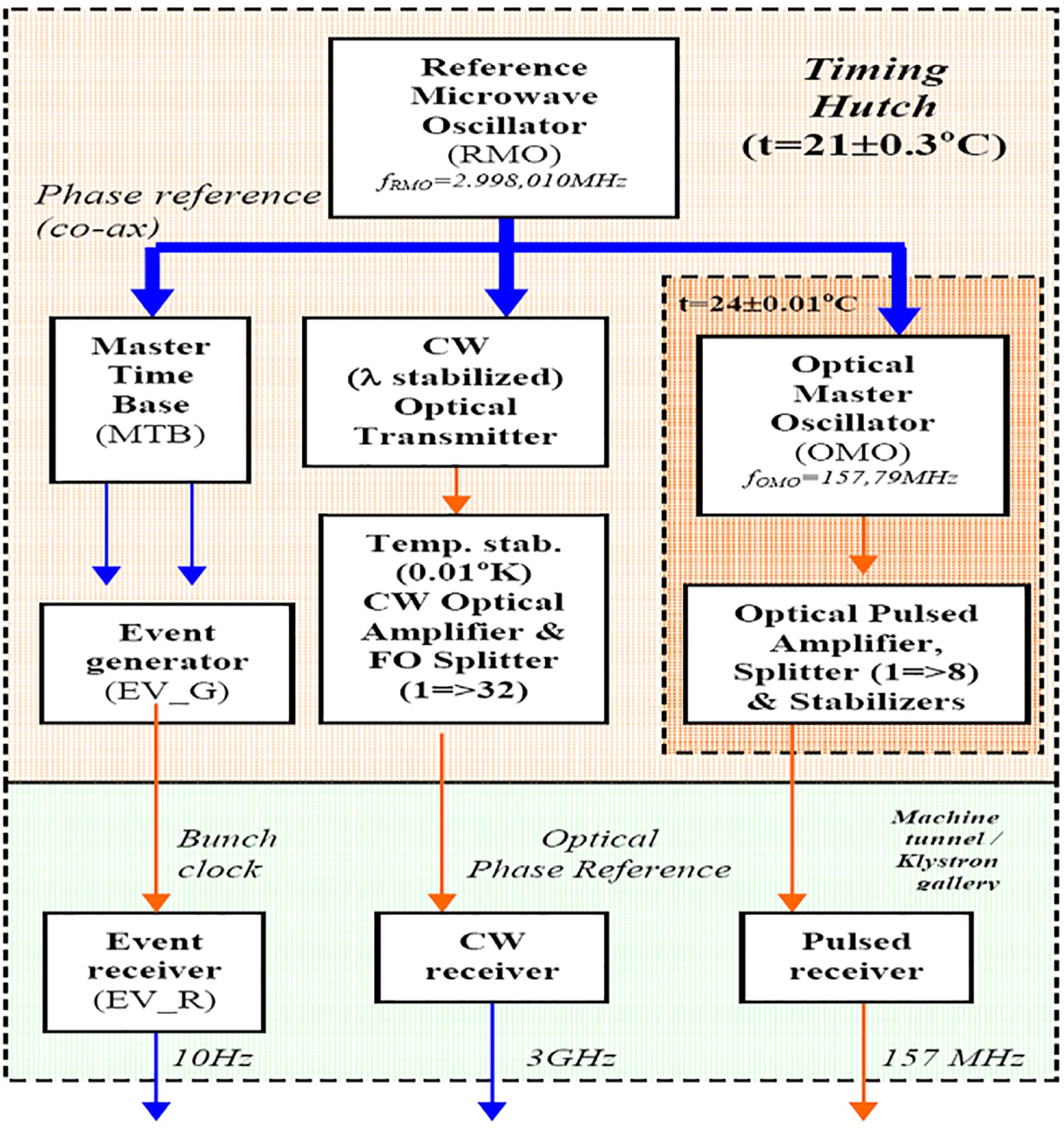
The frequency of the phase reference has been selected to be equal to 2998.01 MHz, which is the frequency of the RF plants (klystrons) feeding the accelerating sections of the LINAC. There are commercially available ultra-low phase noise RF oscillators, which are stable over long time periods. At FERMI, the technical challenge was how to distribute the phase reference signal over the typical distances of an FEL complex (
At FERMI, according to the jitter sensitivity studies, the required stability (jitter and 8-h drift) ranges from the
3.1 The optical timing system layout
For the FERMI optical timing system, we adopted an asymmetric star topology. The timing hutch is located at the center star; it is a temperature-controlled (
For the distribution of the phase reference signal to all the client stations we adopted the Sirocco blown fibers system by Prysmian[
3.2 The pulsed optical timing system
The pulsed optical timing system is shown in Figure
The optical signal of the OMO, amplified by an Er-doped fiber amplifier (EDFA), is split (8 ways) to feed the link stabilization (FLS) units (
The system components, up to the FLS units, are installed in the timing hutch in a temperature-controlled box, stable to 0.1 K; the
3.3 The continuous wave optical timing system
As previously stated, the relative time (i.e., phase) stability of the different RF plants of the LINAC is of paramount importance for the quality (i.e., low energy spread) of the electron bunch. Therefore, to stabilize the phases and amplitudes of the fifteen 3 GHz RF plants, at FERMI the digital Low Level RF (LLRF) system, developed at LBNL[
Any moving part has been omitted in order to improve the overall reliability. A single optical amplifier is fitted to the 32-channel sender unit which is feeding the links and the individual Sync Head/Link stabilizer units to drive local LLRF controllers.
3.4 Characterization of the optical timing system
The most critical part of the optical timing system is the distribution of the pulsed reference signals used for the synchronization of the lasers systems and for the sampling of the electron bunch in the BAM diagnostics. In the seeded FEL, the timing stability of the seed laser (both short and long term) is as crucial as the timing overlap of the beam with the electron bunch.
The design and implementation of the pulsed subsystem has been carried out trying to optimize the relative timing stability between the endpoints of the links, whereas long-term drifts are compensated with an active beam-based feedback system.
During the commissioning of the pulsed optical timing, the validation of the implemented timing distribution has been carried out by comparing the output of a 150 m stabilized fiber link to the local optical reference. This total length does not include the dispersion compensating fiber (DCF), but only the single-mode fiber (SMF) of the link. The optical link, installed in the LINAC tunnel, has been configured in loop back mode such that the optical pulses stream has been made available close to the transmitter end, i.e., in the timing room where the pulsed OMO is installed. An important aspect of this testbed is that the optical fiber was installed in the real accelerator tunnel, with all the EM-noisy RF plants switched on.
The validation consisted in an out-of-loop (OOL) measurement between the stabilized link output and one of the splitter ports, at the star center. The phase comparison between the two signals has been accomplished by means of an optical balanced cross-correlator[
The final characterization of the timing system performance has been carried out by means of an indirect measurement using the BAM diagnostics described later; this kind of verification indeed provides an upper limit of the intrinsic performance of the timing system. This beam-based measurement provides an experimental demonstration of the global stability of FERMI and of its timing system (optical pulsed and optical CW). This measurement shows the relative stability between the pulsed and the CW reference, the first one used to synchronize the photoinjector laser and the BAM station, the second one used to synchronize the RF plants. In Figure
4 The longitudinal diagnostics
Longitudinal diagnostics are instruments developed to perform measurements in the longitudinal axis of the reference system, i.e., in the direction of the electron motion (also referred to as ‘
Longitudinal diagnostics for an FEL can be considered as
At FERMI, several innovative nondestructive longitudinal diagnostics have been engineered and successfully installed on the machine; in this paper, we present the (relative) BLM and the BAM. During the development of these systems, in the framework of the
4.1 The relative BLM
Both the absolute and the relative bunch length measurements are key parameters to the FERMI commissioning and, today, they are extensively used in everyday operation. The FERMI relative BLM design[
The BLM has been designed to perform relative bunch length measurements in the range of bunch length (flat top current profile) from 5 to 0.15 ps, full width (FW). To entirely cover such a broad range of bunch lengths, two coherent radiation sources have been selected. The first source is the coherent synchrotron radiation from the bending magnets of the BC1 compressor. The second is coherent diffraction radiation from a ceramic gap[
The layout of the BLM system installed on BC1 at FERMI is shown in Figure
A detailed study of CSR–CER radiation properties has been performed using the
In Figure
Figure
In Figure
The BLM is based on the detection of coherent radiation whose spectral power depends quadratically on the number of electrons and charge variations affect the output signal. When the BLM is used in a compression feedback these effects are particularly unwanted and a good short- and long-term charge stability is needed. Short-term (shot-by-shot) charge stability is correlated to the gun RF amplitude and phase fluctuations and to the photocathode (PC) laser energy stability; on Fermi, the charge rms is less then 1%. On the other hand, long-term drifts of the charge are controlled by a dedicated slow charge feedback which has the LH charge monitor as sensor and the PC laser UV variable attenuator as the actuator.
4.2 The BAM
The BAM is based on an original idea developed at FLASH/DESY[
As schematically shown in Figure
In a case of overlap, the arrival time of the electron bunch is encoded in the amplitude of one reference laser pulse. Because of the high phase stability of the pulsed reference distribution, such arrival time measurement is highly stable and reliable. In addition, the measurement is nondestructive to the bunch.
At the operating point, one optical pulse of the optical pulsed reference has to time overlap with the zero crossing of the first RF transient from the pick up (modulating signal).
To effectively amplitude modulate the overlapping optical pulse stream, the MZM has to be DC-biased to operate in quadrature such that all the optical laser pulses are modulated to the half amplitude. By doing so, shot-to-shot electron arrival time fluctuations with respect to the optical reference pulses produce a different modulating voltage at the MZM modulating input. Hence electron arrival time fluctuations produce amplitude variations of the optical pulse.
Several BAM stations have been installed on FERMI; two in the LINAC (at BC1 and at BC2) and one before each of the two FEL straight sections, named FEL1 and FEL2, respectively.
Each BAM station consists of two separate units: the front end, installed in the tunnel close to the beam pick up (to minimize the loss on the electrical signal, maximizing the resolution of the BAM diagnostic), and the back end, installed in the service area for the analog to digital conversion of the amplitude modulated pulses and for further processing.
In the BAM front end, shown in Figure
An optical delay line is used for the calibration of the system; the calibration is performed by sweeping the optical pulse around the zero crossing of the first slope of the pick up signal.
The two ADCs located in the back end acquire the peaks and the baseline points in a 512-sample window around the zero crossing; the effective amplitude of each acquired pulse is given by the difference between the peak and the adjacent baseline sample. The result of the calibration is a curve reporting the modulation index (i.e., the ratio between the amplitude of the modulated pulse to the average amplitude of the not modulated pulses in a suitable time window before the modulating event) versus the optical delay line position.
Since the MZM transfer function is temperature dependent, the modulator is temperature stabilized within 100 mK by a Pulse Width Modulation temperature controller, using a thermoelectric element. The unit is remotely controlled, via Ethernet line, where a micro-controller drives all the elements and provides diagnostic information.
The BAM back end (shown in Figure
The modulated pulse signal is split in two and the two outputs are sampled by two 16-bit ADCs working at a rate of 157 MHz. The delay between the two ADC sampling times is kept constant (equal to a few hundreds of picoseconds) to acquire both the peak and the baseline of each pulse to get rid of common mode amplitude fluctuations. The back end is also remotely controlled via Ethernet connection (in this case a real-time communication is needed to implement shot-by-shot feedbacks) and the ADA board is also in charge to drive the SCB.
The resolution of the BAM depends on the slope of the RF transient, on the amplitude noise of the optical pulses and on the overall stability of the acquisition electronics. The amplitude jitter, normalized in percent of the modulation, has been measured on the not modulated pulses; typical values are in the range 0.13%–0.18%.
The resolution of the BAM has been also validated[
An upper limit for the resolution of the diagnostic was estimated neglecting possible contributions to time jitter due to the accelerating sections in between the two diagnostics (installed in two spots of the machine whose distance is roughly 100 m) and assuming independent and identical performance of the two stations (such that their contribution may be added in quadrature). These assumptions are reasonable as the correlation coefficient is always greater than 95%. The result obtained over 1000 shots (shown in Figure
5 The longitudinal feedback systems
Since the beginning of FERMI commissioning (back in 2009–2010), the machine proved to be quite stable in keeping its working point, provided the temperature of the whole facility was kept constant within
5.1 Introduction to FEL feedback systems
The key factors to keep the FEL radiation output stable are both the transverse and the longitudinal (i.e., temporal) stability at the interaction point between the seed laser pulses and the electron bunches, along the modulator undulator. Besides the uncorrelated shot-to-shot noise (that cannot be reduced by beam-based feedback systems), the main cause of FEL output power fluctuations is related to slow thermal drifts which mainly affect the RF plants and the laser systems. These instabilities have frequencies below 0.1 Hz and only beam-based feedbacks effectively damp them out.
In order to maximize the feedback efficiency to dump such kind of Noises, all loops run on a shot-to-shot time base. Sensors and actuators interface to PPC VME front-end computers running Linux with real-time extension and managed by kernel modules. The sensor values are shared among the control system computers by means of a shared memory called network reflective memory (NRM). This software communication protocol, based on Gigabit Ethernet and working at Linux device driver level, has been developed to implement a shared memory across the whole control system, allowing computers to communicate in real time.
The NRM topology is a star-like topology network: a CPU master, every
The system, which supports MIMO models, relies for the static part of the loop on the measure of the linear relation between the inputs and the outputs, which we call the response matrix (RM). The RM is calculated by measuring the perturbations on the sensors produced by each actuator involved in the loop: the actuators are driven sequentially to produce a step or a ramp while the sensors are acquired synchronously to the actuator excitation. At the end of the process, the RM resembles a lower triangular matrix where column values correspond to the distortion measured by the sensors due to the actuator kick. The amplitude of the actuator kicks has to be chosen carefully: a too small kick could be confused in the sensor noise while a large one could induce nonlinear effects on the sensor readings.
While the product between the RM and a combination of actuator values (in order to avoid nonlinear effects the values has to be relatively small) could forecast the effects on sensor readings, the multiplication of the inverted RM with the sensor values returns the list of actuator values which cause the current sensor readings. Practically a feedback system, based on the RM, multiplies the inverted RM by the error (difference between the feedback set point and the actual sensor readings) and subtracts the result from actuator values. The RM inversion is carried out through the singular value decomposition (SVD): in the inversion procedure it is possible to define for each sensor/actuator a weight. The singular values, which come out from the SVD, could be individually weighted as well. Cutoff/Tikhonov singular value weighting strategies are directly integrated in the feedback system.
A low pass filter in series with a proportional integral derivative (PID) controller controls the dynamic part of the loop. Actually the controller parameters are tuned by hand. For every feedback the PID is tuned in order to get a step response without overshoot and, at the same time, try to keep the maximum magnitude of the sensitivity function under ‘one’ across all the loop bandwidth.
All system models involved in feedback systems could be assumed to be equivalent to one delay because the time elapsed from the sensor acquisition to actuator new set-point reaching is within a feedback period (20 ms). The closed loop feedback response could be displaced from the theoretical due to errors in the empirical model, the RM. This happens when the number of input–output increases and the actuators are not independent. In this case a cutoff of the singular values or a Tikhonov regularization of the inverted RM is necessary.
5.2 FERMI longitudinal feedback systems
In FERMI, three different beam-based longitudinal feedback loops are active:
While the energy loops are based on transverse diagnostics, the BPMs, the bunch arrival time and the compression loops use the longitudinal ones (Figure
At FERMI, there are two longitudinal diagnostics based feedbacks: the bunch arrival feedback and the compression feedback.
5.3 Bunch arrival time feedback system
The bunch arrival feedback acquires the arrival time of the electron bunch in BC01 with respect to the FERMI reference timing and keeps it constant, by changing the RF amplitude of the gun. The feedback is based on the principle that the electron bunch time of flight is very sensitive to the RF amplitude in the gun because at such a low energy (
The time of flight of the electron bunch up to BC1 is also strongly dependent of the electron beam energy. In fact, the first bunch compressor converts energy jitter in arrival time jitter so that a decoupling strategy, based on loop gain fine tuning, has to be adopted to avoid cross-talk between bunch arrival and energy feedback in BC1 (as shown in Figure
5.4 The compression factor feedback system
The bunch compressor is a key component of FERMI. It is a magnetic chicane used to produce high peak current electron bunches. The compression factor is tuned by changing different key parameters: the mechanical angle at the chicane, the dipole current, the off-crest phase shift of the S-band sections of LINAC 01 (see Figure
The feedback loop tunes compression factor, measured as the output of a pyroelectric detector, in a small working range. The correlation of the BLM reading with the FEL output power is normally quite strong, so turning off the compression feedback causes large FEL output power oscillation with a frequency below 0.01 Hz (Figure
6 FERMI longitudinal phase space characterization
FERMI is equipped with three RF deflecting cavities[
The working principle of the RF deflector is to provide a null deflecting voltage to the bunch centroid and stretches the electrons linearly from the head to the tail of the bunch, when its RF phase is properly set. In this way electrons transverse displacement are correlated with their longitudinal position along the bunch. Coupling the RF deflector with a diagnostic fluorescent screen allows to characterize the bunch current profile and the time-sliced parameters, as the slice emittance. A time-sliced temporal resolution of about 10 fs has been estimated[
Moreover, as previously mentioned, a detailed knowledge of the longitudinal phase space of the electron bunch (the electron energy distribution as a function of the electron temporal position along the bunch) is of paramount importance to a successful FEL commissioning and operations. At this purpose the beam stretched via the RF deflector can be sent into an energy spectrometer that chromatically disperses electrons in the other (horizontal) transverse plane. The bunch longitudinal phase space can then be visualized on a fluorescent screen system (YAG crystal
Temporal slicing of the data in the acquired image, i.e., selecting small vertical portions of the longitudinal phase space, provides the current profile (red line in Figure
The use of a deflecting cavity after the undulator would permit for a noninvasive and online characterization of the electron beam phase space and FEL induced effects on the electron beam, as currently in use at LCLS[
7 FERMI operation stabilization using the feedback systems
As discussed in the introduction, the main advantage of externally seeded FEL configurations, like the one used at FERMI, concern the control of the FEL process. As a result of the seeding the FEL properties are no longer determined by the shot noise and stochastic effects, but only depend on the electron beam and seed laser properties. To really take advantage of this, it is crucial to be able to control both the seed laser and the electron beam with very high accuracy. A good timing system and dedicated feedbacks are needed to keep both beams, as much as possible, stable in time. In addition to independently stabilize the two beams, that need to interact in the modulator, a perfect synchronization between the two has to be guaranteed.
7.1 Feedback for electron beam stabilization
Beam properties of the electron beam entering into the undulator and producing the FEL radiation are determined by all systems involved from the generation of the electron at the gun and the following acceleration and manipulation along the LINAC. In addition to the stabilized timing system the use of beam-based feedback is needed for compensating long-term drifts that may not be compensated by locally acting feedbacks. The most used beam-based feedbacks at FERMI are:
the electron beam orbit feedback;the beam energy feedback;the beam compression feedback.
7.2 Feedback for seed laser stabilization
In order to transfer to the electron beam the coherent energy modulation, the seed laser pulse needs to be superposed in space and time to the electrons within the modulator. At FERMI, the distance between the last available laser optic and the interaction region is of the order of 10 m. Moreover, another 10 m of optical transport is needed to bring the laser pulse from the laser room to the last injection optics. As a result, keeping micrometer pointing and fs-timing stability of the laser is not a trivial task and it may also be spoiled by slow changes related to temperature changes or other mechanical drifts. Several feedback loops have been implemented on FERMI to keep the laser as much stable as possible; these include[
transverse laser feedback;cross-correlation feedback.
7.3 Feedback e-beam—seed stabilization
Because some of the electron beam properties (i.e., electron beam energy) change along the single electron bunch with time scales of tens of femtoseconds[
Since a small change of the relative timing in between the electron beam and the seed laser can lead to a small change of the FEL emission wavelength[
References
[3] M. Ferianis, A. Borga, A. Bucconi, L. Pavlovic, M. Predonzani, F. Rossi. Proceedings of the 33rd International Free Electron Laser Conference(2012).
[4] G. Penco, E. Allaria, L. Badano, P. Cinquegrana, P. Craievich, M. Danailov, A. Demidovich, R. Ivanov, A. Lutman, L. Rumiz. J. Instrum., 8(2013).
[6] P. Schmüser, M. Dohlus, J. Rossbach, C. Behrens. Springer Tracts in Modern Physics, 258(2014).
[7] R. Bonifacio, N. Narducci, C. Pellegrini. Opt. Commun., 50, 373(1984).
[8] J. Madey. J. Appl. Phys., 42, 1906(1971).
[9] K. Kondratenko, E. Saldin. Part. Accel., 10, 207(1980).
[11] L. H. Yu. Phys. Rev. A, 44, 5178(1991).
[12] L. Yu. Nucl. Instrum. Methods Phys. Res. A, 393, 96(1997).
[17] J. Byrd, L. Doolittle, A. Ratti, J. W. Staples, R. Wilcox, M. Stettler, G. D’Auria, M. Ferianis, M. Milloch, A. Rohlev. Proceedings of the 22nd Particle Accelerator Conference(2007).
[18] M. Ferianis. IEEE Proceedings of the 23rd International Linear Accelerator Conference(2006).
[19] J. M. Byrd, L. Doolittle, A. Ratti, J. W. Staples, R. Wilcox. IEEE Proceedings of the 23rd International Linear Accelerator Conference(2006).
[20] J. Kim, J. A. Cox, J. Chen, F. X. Katner. Nat. Photonics, 2, 733(2008).
[24] B. Steffen, S. Casalbuoni, P. Schmuser, S. Simrock, M. Tonutti, A. Winter, T. Korhonen, T. Schilcher, V. Schlott, H. Sigg, D. Suetterlin. Proceedings of EPAC 2004(2004).
[25] A. Winter, F. Lohl, F. Ludwig, H. Schlarb, B. Schmidt, P. Schmuser. Proceedings of EPAC 2006(2006).
[26] G. A. Loew, O. H. Altenmueller.
[27] I. Ben-Zvi, J. X. Qiu, X. J. Wang. Proceedings of 17th Particle Accelerator Conference(1997).
[28] M. Veronese, R. Appio, P. Craievich, G. Penco. Phys. Rev. Lett., 110(2013).
[29] H. Loos, T. Borden, P. Emma, J. Frisch, J. Wu. Proceedings of PAC07(2007).
[30] R. Appio.
[31] O. Grimm.
[33] L. Pavlovic, A. O. Borga, M. Ferianis, M. Predonzani, F. Rossi. Proceedings of the Beam Instrumentation Workshop(2010).
[34] A. O. Borga, R. De Monte, M. Ferianis, L. Pavlovic, M. Predonzani. Proceedings of the Beam Instrumentation Workshop(2010).
[35] E. Ferrari, E. Allaria, P. Cinquegrana, M. Ferianis, L. Froelich, L. Giannessi, G. Penco, M. Predonzani, F. Rossi, P. Sigalotti, M. Veronese. Proceedings of the IBIC’13(2013).
[37] M. Rohrs, C. Gerth, H. Schlarb, B. Schmidt, P. Schmüser. Phys. Rev. ST Accel. Beams, 12(2009).
[38] Y. Ding, C. Behrens, P. Emma, J. Frisch, Z. Huang, H. Loos, P. Krejcik, M.-H. Wang. Phys. Rev. ST Accel. Beams, 14(2011).
[39] P. Craievich, S. Biedron, C. Bontoiu, S. Di Mitri, M. Ferianis, M. Veronese, M. Petronio, D. Alesini, L. Palumbo. Proceedings of the FEL10 Conference(2012).

Set citation alerts for the article
Please enter your email address
© Copyright 2018-2021 | Chinese Laser Press. All Rights Reserved 沪ICP备15018463号-20