Abstract
By controlling the wavelength and power of multiple light sources, we have realized a highly flexible Nyquist pulse generation scheme, in which the pulse repetition frequency, pulse multiplication factor, waveform envelope shape, and duty cycle are all tunable. By modulating the 3.2 GHz RF signal, we experimentally generated Nyquist pulses with repetition rates of 6.4 GHz and 9.6 GHz, a rectangular wave with a duty cycle of 0.26, and a sawtooth wave with a duty cycle of 0.52.Nyquist pulse refers to a pulse that has a sinc function shape in the time domain, and the corresponding spectrum shape is nearly rectangular[1]. Transmission and encoding with Nyquist pulses can suppress inter-symbol interference[2] and, at the same time, can provide maximum spectrum utilization[3], which is of great significance in coherent optical communications[4–6]. In addition, due to the unique spectral shape of Nyquist pulses, dense wavelength division multiplexing benefits from it significantly, and channel capacity can be improved[7,8]. Moreover, Nyquist pulses can also improve the performance of microwave photonic filters[9] and optical analog-to-digital converters (ADCs)[10,11]. Other applications such as all-optical signal processing[12] and light storage[13,14] have also been demonstrated with Nyquist pulses.
The advantages of Nyquist pulses have attracted many researchers, and many methods have been reported to generate Nyquist pulses. Nyquist pulses can be electronically obtained by an arbitrary waveform generator[15]. However, due to the bandwidth of electrical devices, this method is difficult to generate high-repetition-rate pulses. The method of obtaining pulses optically has better performance in terms of pulse width and repetition frequency than the electrical methods. Common practices in the optical domain are to generate pulses by optical parametric amplification[16] or by shaping the comb of a mode-locked laser[17–20]. However, these methods are either limited by a complex experimental setup or the performance of optical filters, and it is still challenging to generate ideal Nyquist pulses in practical applications.
Modulation-based Nyquist pulse generation is another important method. Based on the time-frequency characteristics of Nyquist pulses, the researchers obtained a flat optical frequency comb (OFC) by cascading intensity modulators to generate nearly ideal Nyquist pulses[21]. In principle, a single modulator can generate three linear-phase flat optical comb lines. A single dual-parallel Mach–Zehnder modulator (DPMZM) can generate five linear-phase flat optical comb lines[22]. Through different combinations of a Mach–Zehnder modulator (MZM) and a DPMZM, optical combs with 3, 5, and 9 flat linear-phase comb lines can be obtained[23]. In these works, the repetition rate is determined by the minimum modulation frequency. Due to the bandwidth limitation of the electro-optic modulator, it is not possible to increase the repetition rate of the pulses to a very high frequency. Therefore, it is necessary to find other methods to increase the repetition frequency of the Nyquist pulses.
Sign up for Chinese Optics Letters TOC. Get the latest issue of Chinese Optics Letters delivered right to you!Sign up now
The time-wavelength interleaved system can be used to increase the repetition frequency of the pulse train, thereby improving the performance of the ADC system[24,25]. A dispersion element with a linear chirp (such as a dispersion fiber) can be used to achieve continuous mapping of time to wavelength, which delays different wavelengths by different amounts[26]. Inspired by this concept, this paper proposes a flexible and tunable time-wavelength interleaving system based on the Nyquist pulse.
In this work, we propose a flexible Nyquist pulse generation method based on precise control of multiple wavelengths. Multiple light sources with different wavelengths are injected into two cascaded intensity modulators first to generate a flat OFC and Nyquist pulses. By properly tuning the wavelengths and injected light power, different pulse separation and envelopes can be obtained after light propagating through a dispersion fiber. This method allows highly flexible control of the pulse train repetition rate and envelope and can benefit the applications such as non-uniform photonic sampling and photonic signal processing.
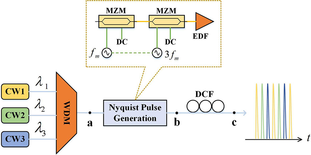
The experimental setup is shown in Fig. 1. This scheme includes three stages: the light source stage, the Nyquist pulse generation stage, and the dispersion stage. The light source stage combines a few continuous wave (CW) laser sources with a wavelength division multiplexer (WDM). Each laser source has tunable wavelength and tunable power. The Nyquist pulse generation stage is composed of two cascaded MZMs. Two phase-locked RF frequencies and are applied to the MZMs. The RF frequencies share a same reference and have the frequency stability of ∼1 ppm (parts per million). Our previous work has shown that when a single CW is injected, this modulation scheme can generate a periodic Nyquist pulse train with the repetition rate of [21]. Its corresponding spectrum is an OFC with nine flat comb lines. Therefore, if multiple wavelengths are injected simultaneously, multiple overlapped Nyquist pulse trains with the same repetition rate of will be generated. In the spectrum, multiple OFCs will be obtained. The dispersion stage is a pool of dispersion compensation fiber (DCF). With this stage, overlapped Nyquist pulse trains can be separated in the time domain due to the different propagation speeds at different wavelengths. It is easy to discover that the separation time between Nyquist pulse trains is determined by the wavelength separation in the light source stage. The envelope of the pulse train is determined by the light power in the light source stage. With this simple scheme, many useful functions can be realized, such as multiplication of repetition rate and arbitrary waveform (envelope) generation.

Figure 1.Experimental setup diagram.
A theoretical analysis is first performed. A detailed analysis of OFC and Nyquist pulse generation has been provided in previous work[27]. The expression of a periodic Nyquist pulse train is given by[21]
Equation (1) is a series of functions with equal amplitude in the frequency domain, where is the spacing of comb lines, and is the number of comb lines.
The effect of the dispersion stage is given by[25]where is the time delay between two wavelengths, is the wavelength difference, and is the group delay dispersion. In the experiment, is a fixed value of 81.4 ps/nm. Assuming that the wavelength interval among the light sources is , and the repetition rate of the Nyquist pulse generated by a single-wavelength light source after modulation is , the pulse sequences are “inserted” into the original pulse sequence at equal intervals, as given by Eq. (3). The system works as frequency multiplication with the multiplication number of . The repetition rate of the generated pulse train is . There is no requirement of precise control of GDD because laser wavelength can be tuned by
Figure 2 illustrates the evolution of the spectra and pulses when the entire system is operating. Figs. 2(a)–2(c) are the spectra at points a, b, and c denoted in Fig. 1. Figures 2(d)–2(f) are the corresponding waveforms in the time domain at these three points.
Figure 2.The process of spectrum and pulse evolution of each point. (a) and (d), respectively, correspond to the spectrum and pulse of point a in Fig. 1; (b) and (e), respectively, correspond to the spectrum and pulse of point b in Fig. 1; (c) and (f), respectively, correspond to the spectrum and pulse of point c in Fig. 1.
Theoretically, the larger the number of light sources, the larger the multiplication factor, and the richer the waveform shape that can be generated. However, to prevent aliasing between pulses, Eq. (4) must be satisfied, where is the cross-zero pulse width of the Nyquist pulse:
Cross-zero pulse width is given by where is the number of comb lines in the Nyquist pulse generation stage. When the number of the comb lines is nine, the number of light sources is a maximum of four.
In the Nyquist pulse generation stage, each MZM generates three phase-locked OFCs. Due to the frequency relationship between the two RF signals, a nine-line flat OFC can finally be generated in the spectrum, as shown in Fig. 3(a). The corresponding Nyquist pulses in the time domain are shown in Fig. 3(b). The additional advantage of this solution is that the repetition rate of the Nyquist pulse can be changed with the frequency of the RF signal, so it is adjustable. The maximum repetition rate is currently limited by the available maximum modulation frequency and the maximum bandwidth of the modulator. So, for 100 GHz () maximum frequency/bandwidth, the maximum repetition rate would be 33.3 GHz.
Figure 3.(a) Spectrum of nine-line optical frequency comb spaced at 3.2 GHz. (b) Corresponding Nyquist pulse sequence with a repetition rate of 3.2 GHz.
Figure 4.(a) Modulation depth versus DC bias. (b) Out-of-band suppression ratio versus modulation depth.
Pulse stability is mainly determined by the light source stability, modulator working-point stability, and modulation signal stability. The stability of the light source is about 1 pm/10 h. The operating point of the modulator will drift with time, but it can be eliminated by automatic feedback control. The stability of the modulation signal is 1 ppm, so the frequency fluctuation is one millionth of the modulation frequency. Therefore, the above devices have high stability, and Nyquist pulses also have high stability.
The two working modes of the system are then investigated. The first is the frequency multiplication mode, in which the pulse train is “inserted” into the original pulse train at equal intervals. The wavelengths between the light sources are nearly equally spaced based on Eq. (2), and the power of the light sources is also equal. We experimentally obtained a Nyquist pulse train with frequency multiplication factors of 2 and 3.
As shown in Fig. 5, a demonstration of repetition rate doubling is first provided. Figures 5(a) and 5(b) show the OFC spectra with nine comb lines at two different wavelengths, and the flatness of the OFC is 2.5 dB. The wavelength dependent response of the modulators slightly increases the flatness. The wavelength interval between the two light sources is 1.8 nm. The OFC spacing is 3.2 GHz. There is weak wavelength dependence in the modulator, so the OFC spectra at two wavelengths are slightly different. The OBSR is 20 dB. After the dispersion stage, the pulses are interleaved, and the repetition rate is doubled to 6.4 GHz, as shown in Fig. 5(c).
Sign up for Chinese Optics Letters TOC. Get the latest issue of Chinese Optics Letters delivered right to you!Sign up now
Figure 5.Spectra generated by two light sources of (a) 1549.6 nm and (b) 1551.4 nm. (c) Nyquist pulse train with the repetition rate of 6.4 GHz.
When the number of light sources is increased to three, the pulse train with a tripled repetition rate can be achieved, as shown in Fig. 6(a). The wavelength interval between the three light sources is 1.2 nm. The OFC spacing is 3.2 GHz. The flatness of the OFC is 2 dB. The OBSR is 20 dB. The Nyquist pulse train is shown in Fig. 6(b). The pulse repetition rate is 9.6 GHz.
Figure 6.(a) Spectrum generated when three light sources are applied. (b) Nyquist pulse train with the repetition rate of 9.6 GHz.
The non-returned zero is caused by a few effects, including the bias current of the photodetector, the power combination of pulses, limited extinction ratio of modulators, etc. The bias current of the photodetector lifts the DC level of the total signal, which happens only in the electrical signal and can be removed by a DC blocker. The power combination of pulses is that the tailing power of a pulse can lift the level of another pulse when these two pulses are close to each other. This can be improved by matching the zero points of these pulses in the time domain. The extinction ratio of modulators also limits the minimum power level, which can be improved by using high-extinction-ratio modulators.
When the Nyquist pulse trains are not “inserted” into the original pulse train at equal intervals, the system works in the waveform generation mode. Equation (8) describes the relation between the duty cycle and the number of light sources :
When the optical power between the light sources is equal, the generated pulse envelope is rectangular, as shown in Fig. 7(a). When the optical power between the light sources is not equal, the envelope shape of the generated pulse train can also be configured. Figure 7(b) shows an example of a sawtooth wave. The duty cycle can be calculated by Eq. (8). This means that by adjusting the wavelength interval between light sources, rectangular waves with different duty cycles can be generated. As a two-wavelength example shown in Fig. 8, a duty cycle of 0.26 is shown, and the corresponding wavelength difference is 1 nm.
Figure 7.Principle of generating (a) rectangular wave and (b) sawtooth wave.
Figure 8.(a) Rectangular waves with a repetition rate of 3.2 GHz and duty cycle of 0.26. (b) A zoomed view of a single period.
Sawtooth waves can be obtained when the number of the light sources is three, and the duty cycle can be calculated by Eq. (8). Two sawtooth waves with the same repetition rate of 3.2 GHz and duty cycles of 0.52 (two wavelengths) and 0.67 (three wavelengths) are generated, respectively, as shown in Fig. 9. The duty cycle of the waveforms can be modified by changing the number of light sources and the interval between wavelengths. More precise waveform envelopes can be obtained if more light sources are applied. Other waveforms such as a triangle wave can also be obtained similarly.
Figure 9.Sawtooth waveforms with a repetition rate of 3.2 GHz and duty cycles of (a) 0.52 and (b) 0.67.
Coherent combining of multiple combs is also a potential application. Then, precise frequency and phase control of multiple light sources is required.
In conclusion, a highly flexible Nyquist pulse generator based on time-wavelength interleaving technology is demonstrated. By changing the wavelength and power in each light source, repetition rate multiplication and arbitrary waveform (envelope) generation are achieved. The scheme has high tunability in many aspects including the repetition rate, waveform, number of pulses in one period, pulse interval, etc. In the future, MZMs can be replaced with DPMZMs for wider OFC and narrower pulse duration. This work demonstrates a highly programmable pulse train generation method, which can benefit photonic signal processing.
References
[1] A. Assalini, A. M. Tonello. IEEE Commun. Lett., 8, 87(2004).
[2] N. C. Beaulieu, C. C. Tan, M. O. Damen. IEEE Commun. Lett., 5, 367(2001).
[3] M. Nakazawa, T. Hirooka, P. Ruan, P. Guan. Opt. Express, 20, 1129(2012).
[4] R. Schmogrow, M. Winter, M. Meyer, D. Hillerkuss, S. Wolf, B. Baeuerle, A. Ludwig, B. Nebendahl, S. Ben-Ezra, J. Meyer, M. Dreschmann, M. Huebner, J. Becker, C. Koos, W. Freude, J. Leuthold. Opt. Express, 20, 317(2012).
[5] R. Schmogrow, D. Hillerkuss, S. Wolf, B. Bäuerle, M. Winter, P. Kleinow, B. Nebendahl, T. Dippon, P. C. Schindler, C. Koos, W. Freude, J. Leuthold. Opt. Express, 20, 6439(2012).
[6] K. Harako, D. Seya, T. Hirooka, M. Nakazawa. Opt. Express, 21, 21062(2013).
[7] M. S. Erkılınc, S. Pachnicke, Z. Li, H. Griesser, B. C. Thomsen, P. Bayvel, R. I. Killey. J. Lightw. Technol., 33, 15(2015).
[8] D. Hillerkuss, R. Schmogrow, M. Meyer, S. Wolf, M. Jordan, P. Kleinow, N. Lindenmann, P. C. Schindler, A. Melikyan, X. Yang, S. Ben-Ezra, B. Nebendahl, M. Dreschmann, J. Meyer, F. Parmigiani, P. Petropoulos, B. Resan, A. Oehler, K. Weingarten, L. Altenhain, T. Ellermeyer, M. Moeller, M. Huebner, J. Becker, C. Koos, W. Freude, J. Leuthold. J. Opt. Commun. Netw., 4, 715(2012).
[9] V. R. Supradeepa, C. M. Long, R. Wu, F. Ferdous, E. Hamidi, D. E. Leaird, A. M. Weiner. Nat. Photon., 6, 186(2012).
[10] V. Vercesi, D. Onori, J. Davies, A. Seeds, C. P. Liu, M2G-3(2018).
[11] J. Yang, S. Li, X. Xiao, D. Wu, X. Xue, X. Zheng. Chin. Opt. Lett., 16, 060605(2018).
[12] M. Santagiustina, S. Chin, N. Primerov, L. Ursini, L. Thévenaz. Sci. Rep., 3, 1594(2013).
[13] T. Schneider, K. Jamshidi, S. Preußler. J. Lightw. Technol., 28, 17(2010).
[14] S. Preußler, K. Jamshidi, A. Wiatrek, R. Henker, C. A. Bunge, T. Schneider. Opt. Express, 17, 15790(2009).
[15] R. Schmogrow, D. Hillerkuss, S. Wolf, B. Bäuerle, M. Winter, P. Kleinow, B. Nebendahl, T. Dippon, P. C. Schindler, C. Koos, W. Freude, J. Leuthold. Opt. Express, 20, 6439(2012).
[16] A. Vedadi, M. A. Shoaie, C.S. Brès. Opt. Express, 20, 27344(2012).
[17] G. Bosco, A. Carena, V. Curri, P. Poggiolini, F. Forghieri. IEEE Photon. Technol. Lett, 22, 1129(2010).
[18] T. Hirooka, P. Ruan, P. Guan, M. Nakazawa. Opt. Express, 20, 15001(2012).
[19] M. Nakazawa, M. Yoshida, T. Hirooka. Optica, 1, 15(2014).
[20] S. Chen, W. Hu, Y. Xu, Y. Cai, Z. Wang, Z. Zhang. Chin. Opt. Lett., 17, 121405(2019).
[21] M. A. Soto, M. Alem, M. A. Shoaie, A. Vedadi, C. S. Brès, L. Thévenaz, T. Schneider. Nat. Commun., 4, 2898(2013).
[22] J. Wu, J. Zang, Y. Li, D. Kong, J. Qiu, S. Zhou, J. Shi, J. Lin. Opt. Express, 22, 20463(2014).
[23] Y. Li, J. Wu, Y. Ji, D. Kong, W. Li, X. Hong, H. Guo, Y. Zuo, J. Lin. Opt. Express, 20, 24754(2012).
[24] J. U. Kang, R. D. Esman. Electron. Lett., 35, 60(1999).
[25] P. W. Juodawlkis, J. C. Twichell, G. E. Betts, J. J. Hargreaves, R. D. Younger, J. L. Wasserman, F. J. O’Donnell, K. G. Ray, R. C. Williamson. IEEE Trans. Microw. Theory Tech., 49, 1840(2001).
[26] M. Y. Frankel, J. U. Kang, R. D. Esman. Electron. Lett., 33, 2096(1997).
[27] S. Liu, K. Wu, L. Zhou, L. Lu, B. Zhang, G. Zhou, J. Chen. IEEE J. Sel. Top. Quantum Electron, 26, 8300208(2020).