
Xiaoying He, Mengyuan Li, Lan Rao, "Underwater Bessel-like beams with enlarged depth of focus based on fiber microaxicon," Chin. Opt. Lett. 20, 072601 (2022)
- Chinese Optics Letters
- Vol. 20, Issue 7, 072601 (2022)
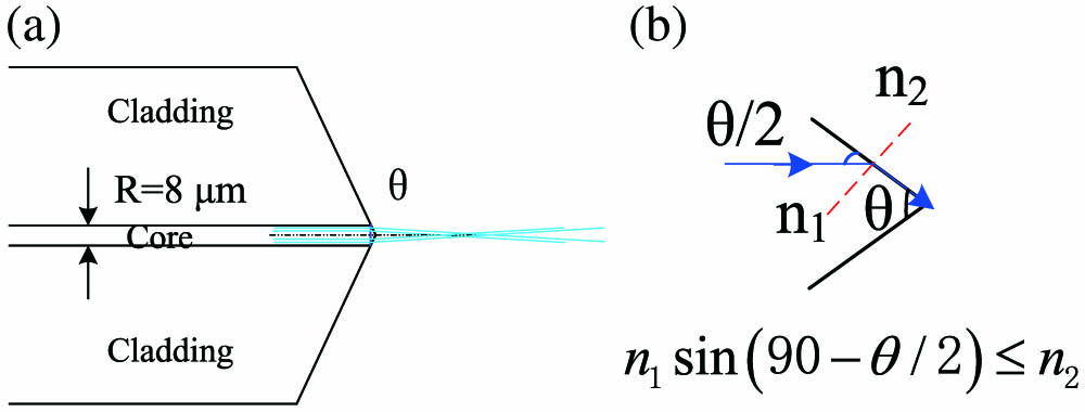
Fig. 1. (a) Schematic diagram of the fiber microaxicon, (b) formation principle of the refraction angle for the fiber microaxicon.
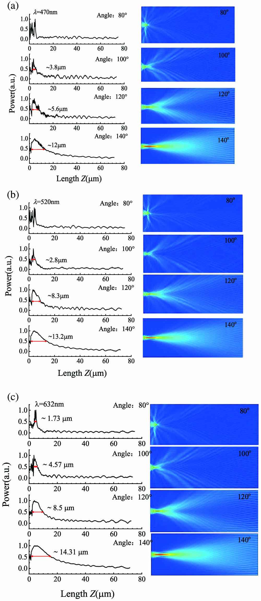
Fig. 2. Power distribution of Bessel-like beams from fiber microaxicons with different cone angles of 80°, 100°, 120°, and 140° at different visible wavelengths of (a) 470 nm, (b) 520 nm, and (c) 632 nm in the air.
Fig. 3. Power distribution of Bessel-like beams underwater from fiber microaxicons with different cone angles of 40°, 60°, 80°, 100°, 120°, and 140° at different wavelengths of (a) 470 nm, (b) 520 nm, and (c) 632 nm.
Fig. 4. Normalized FWHM and DOF as functions of fiber microaxicons cone angle θ. The solid black lines represent the value of DOF, and the dotted lines represent the value of FWHM. (a) Bessel-like beams generated in the air; (b) Bessel-like beams generated underwater.
Fig. 5. Transverse power distributions of Bessel-like beams with the blue (470 nm), green (520 nm), and red (632 nm) lights generated by the fiber microaxicons underwater for propagation at (a) 500 m, (b) 2000 m, and (c) 4000 m.
Fig. 6. Transverse power distributions of Gaussian beams with the blue (470 nm), green (520 nm), and red (632 nm) lights generated by the fiber microaxicons underwater for propagation at 500 m.


Set citation alerts for the article
Please enter your email address

© Copyright 2018-2021 | Chinese Laser Press. All Rights Reserved 沪ICP备15018463号-20