The cavity ring-down (CRD) technique is adopted for simultaneously measuring - and -polarization reflectivity of highly reflective coatings without employing any polarization optics. As the - and -polarized light trapped in the ring-down cavity decay independently, with a randomly polarized light source the ring-down signal recorded by a photodetector presents a double-exponential waveform consisting of ring-down signals of both - and -polarized light. The - and -polarization reflectivity values of a test mirror are therefore simultaneously determined by fitting the recorded ring-down signal with a double-exponential function. The determined - and -polarization reflectivity of 30° and 45° angle of incidence mirrors are in good agreement with the reflectivity values measured with the conventional CRD technique employing a polarizer for polarization control.
Highly reflective (HR) mirrors[1] have been widely used in a variety of fields, such as high power laser systems[2], laser gyroscopes[3], and gravitational-wave detectors[4], etc.[5]. The accurate and reliable characterization of mirror reflectivity is of central importance for these applications. The reflection of light on an interface between two dielectric media at off-normal incidence is in general anisotropic, as shown by Fresnel’s laws. Consequently, the - and -polarization-dependent reflection coefficients of HR mirrors are different at large angles of incidence (AOIs). Normally polarization-dependent reflectances of optical components are measured with spectrophotometry-based[6,7] instruments by rotating a polarizer, such as Perkin Elmer Lambda 900/1050 or Aligent Cary 5000/7000 spectrophotometers. The typical uncertainties of spectrophotometers for reflectance measurements are approximately . Due to the uncertainty limitations, spectrophotometry is not capable of measuring reliably reflectances higher than 99.9%. On the other hand, the cavity ring-down (CRD) technique is an appropriate method to measure reflectance that is higher than 99.9% with a typical measurement uncertainty of 1 ppm, or even less[8–11].
In the past, to accurately measure the - and -polarization reflectances of HR mirrors at large AOIs, in the CRD technique a high-extinction-ratio polarizer was employed to generate linearly polarized light before the light enters the optical cavity. Via rotating the polarizer to generate - and -polarized light beams, the - and -polarization-dependent reflection coefficients and of HR mirrors are determined separately[12]. More recently, the polarization-dependent CRD technique was also used to measure linear dichroism in atomic systems[13], residual reflectivity[14], electro-optic and magneto-optic phenomena[15], absorption of surfaces and condensed matter (with evanescent-wave CRD spectroscopy[16]), ultralow supermirror birefringence (with the polarimetric differential CRD technique[17]), and linear birefringence and polarization-dependent loss[18], etc. In these CRD experiments, polarization-dependent loss measurements were fulfilled by putting a polarization-selective optical element at the exit of the cavity so as to isolate the two eigenstates of the resonator. These application examples are all measuring simultaneously the - and -polarization optical losses with polarization optics. Successful implementation required careful adjustment of the polarization-selective elements.
The polarization states of light should be considered as a source of uncertainty when accurate measurements are needed and the degree of polarization of incident light is unknown. In this Letter, the CRD technique[19–22] is adopted for accurate and simultaneous measurements of and of HR mirrors without employing any polarization optical components. By employing a randomly polarized laser beam as the light source and fitting the recorded ring-down signal to a double-exponential function to extract simultaneously the ring-down time of - and -polarized light, the - and -polarization reflectances and of HR mirrors are determined simultaneously with high precision.
Sign up for Chinese Optics Letters TOC. Get the latest issue of Chinese Optics Letters delivered right to you!Sign up now
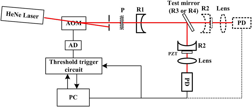
A continuous-wave (cw) CRD technique is used in the experiment. The experimental setup is schematically shown in Fig. 1. The light source is a randomly polarized He–Ne laser with a 632.8 nm wavelength and 10 mW output power. An acousto-optical modulator (AOM) acts as an optical switch for stopping laser beams from entering the ring-down cavity (RDC). A square-wave signal at 100 Hz generated by a computer-controlled function generation (FG) card and duty cycle controlled by a threshold circuit (TC) are used to modulate the voltage of the AOM driver. The deflected beam is injected into the RDC for ring-down time measurements. The initial RDC is formed by two plano–concave mirrors R1 and R2 (called cavity mirrors) with a diameter of 25.4 mm and a radius of curvature . The resonance of the input laser with the resonance modes of RDC is achieved by modulating the cavity length via applying a triangle wave to three piezoelectric transducers attached to one cavity mirror mount. The light that leaks out of cavity mirror R2 is focused onto a photodetector (PD) for ring-down signal detection. When the detected signal amplitude exceeds a preset threshold, the laser beam is switched off within less than 100 ns by blocking the RF radiation used to drive the AOM that otherwise deflects light into the cavity, and the PD recorded ring-down signal is digitized by a data acquisition (DA) card for data processing.
To simultaneously measure the - and -polarization reflectances of test mirrors with this CRD configuration, the ring-down signal of the initial RDC is first recorded. Then a test mirror is inserted into the initial RDC with the required AOI to form a test RDC, as shown in Fig. 1. The ring-down signal of the test RDC is then recorded for data processing. For comparison, the - and -polarization reflectances of test mirrors are also independently measured. In this case, a high extinction-ratio () polarizer is inserted in front of cavity mirror R1 for polarization selection.
Two plano test mirrors R3 and R4 used in the experiment are HR multilayers for 633 nm applications for 45° and 30° AOIs coated on fused silica substrates (Corning 7980). The diameter and thickness of the test mirrors are 20 and 5 mm, respectively. As an example, Fig. 2 shows the theoretical reflectance spectrum of the 45° AOI test mirror designed with Optilayer software which is based on well-known optical coating design theory[23]. The multilayer design is Sub/(HL)^15 H/Air, with H and L represent the layers of high- and low-refractive index materials, and Sub and Air represent the substrate and air, respectively. It is an HR mirror with 15 pairs of HL layers and one additional H top layer. The refractive indices of the air and substrate are 1 and 1.459, respectively, and the refractive indices of the high- and low-refractive index materials are 2.115 and 1.457, respectively. At 633 nm wavelength, the theoretical reflectances for - and -polarization are 99.9999% and 99.9883%, respectively, as shown in Fig. 2(b). The test mirrors are prepared with a magnetron sputtering coating equipment (HELIOS 400, Leybold Optics, Germany).
Figure 2.(a) Theoretical reflectance spectrum of a test mirror in 550–750 nm. (b) Expanded view in 600–670 nm.
At first, the average reflectance (defined as , where and are the reflectances of the two cavity mirrors, respectively) of cavity mirrors is measured and its dependence on polarization is investigated with the initial RDC configuration. The cavity length of the initial RDC is 0.41 m. The recorded ring-down signal is well fitted by a single-exponential function and the reflectance of the cavity mirrors is determined to be 99.99454%, independent of the polarization state. The failure of fitting the recorded ring-down signal to a double-exponential function is also a clear indication that the reflectance of the cavity mirrors is isotropic (independent of the polarization state), as the AOI is exactly zero. The independence of the cavity mirror reflectance on the polarization state is further experimentally verified. The orientation of the polarizer is rotated to change the polarization state (from vertical to parallel) of light entering the initial RDC. The cavity mirror reflectance is measured as a function of polarization orientation and the results are shown in Fig. 3. The cavity mirror reflectance is determined via , where is the ring-down time of the initial RDC determined by fitting the recorded ring-down signal to a single-exponential function[19] and is the speed of light. The reflectance and corresponding uncertainty for each polarizer orientation are the average and standard deviation of four hundred repeat measurements, respectively. Clearly, the cavity mirror reflectance is independent of the polarization state of the incident laser beam. The reflectance averaged over different polarization orientations is , which is in excellent agreement with the value 99.99454%, determined with the randomly polarized light and without inserting the polarizer, indicating the high precision and reliability of CRD for reflectivity measurements. The experimental results show that the birefringence of cavity mirrors is negligible in our experiments[24,25].
Figure 3.Measured average reflectance of cavity mirrors versus angle of polarizer orientation.
Test mirror R3 with an AOI of 45° is then inserted into the RDC to form a folded test RDC with the polarizer removed. The test cavity length is 0.603 m. As the light source is randomly polarized, it has nonzero - and -polarization components. Therefore, two mutually orthogonal eigenstates (-polarization and -polarization) are independently excited in the RDC. Consequently, the ring-down signal can be expressed as where and represent the ring-down signals of - and -polarized light, respectively, represents a DC offset of the ring-down signal, and and represent - and -polarization ring-down times of the test RDC, respectively. The phase shift between - and -polarized light is considered in and . Equation (1) presents a double-exponential function. The ring-down times and can be acquired by fitting the recorded ring-down signal to Eq. (1).
Once the ring-down signals of the initial and test RDCs are measured and the ring-down times are extracted, the reflectances and of the test mirror can be determined as For the 45° AOI test mirror R3, one of the measured ring-down signals in a logarithmic scale is shown in Fig. 4(a). By fitting the averaged ring-down signal measured with random polarization to Eq. (1), the ring-down times and of the test RDC are simultaneously determined to be 30.66 and 10.36 μs, respectively. Consequently, the - and -polarization reflectances and of the 45° AOI test mirror are determined via Eq. (2). The statistical and values of five measurements are and , respectively. To prove the correctness of the - and -polarization reflectances determined with the proposed method, the - and -polarization reflectances of test mirror R3 are also measured with the conventional CRD technique with putting a polarizer in front of the test RDC. Completely -polarized and -polarized beams are obtained by carefully adjusting the orientation of the polarizer. The ring-down signals of the test RDC for complete -polarization and -polarization are also shown in Fig. 4(a). By fitting the ring-down signals to a single-exponential function, the ring-down times and of the test RDC are determined to be 29.91 and 9.89 μs, respectively. Again, the statistical and values of five measurements are and , respectively. The differences of and between the values determined by the proposed (double-exponential fit) and conventional (single-exponential fit) CRD techniques are 1 and 9 ppm, respectively. These results are listed in Table 1.
Figure 4.Ring-down signal of the test RDC on a logarithmic scale for different polarization states (a) 45° AOI mirror, (b) 30° AOI mirror.
Test mirror R4 (with 30° AOI) is measured in a similar way. The averaged ring-down signals of the test RDC for random, complete -, and complete -polarizations are shown, respectively, in Fig. 4(b) and the determined reflectance values are also listed in Table 1. The and values determined by the random-polarization CRD approach are and , respectively, while those determined by the conventional CRD method are and , respectively. The corresponding differences of and are 2 and 30 ppm, respectively, indicating the correctness of the reflectance values determined by the random polarization CRD approach. From Table 1, the double- and single-exponential function fittings give comparable uncertainties, indicating that both techniques have comparable accuracies. As expected, the difference increases with the decreasing reflectance of the test mirror, and the difference for the -polarization reflectance is larger than that for the -polarization reflectance.
It is well known from optical interface physics that off-normal incidence dielectric mirrors typically have a lower reflectance for -polarized light than they do for -polarized light. The common ground of CRD is that a higher mirror reflectance results in more precise measurements. Thus, the uncertainty of the -polarization reflectance is larger than that of the -polarization reflectance. Moreover, due to the lower -polarization reflectance, the finesse of the -polarization cavity is lower than that of the -polarization cavity. Consequently, the -polarization component of the recorded ring-down signal is lower than the -polarization components, so that the signal to noise ratio of the -polarized ring-down signal is lower than that of the -polarized ring-down signal. For both reasons, the measurement accuracy of the -polarization reflectance is lower than that of the -polarization reflectance, as the results presented in Table 1 show. Still, the accuracy is sufficiently high for reliable measurements of the high - and -polarization reflectances of HR mirrors.
For the simultaneous determination of the - and -polarization reflectances with the double-exponential function fitting, the reliability of simultaneous determination relies on the uniqueness of the fitted parameters. In the following, the uniqueness is investigated by analyzing the sensitivity of mean square variance to the fitted parameters. In the analysis, the experimental data (with measurement errors) are fitted to a double-exponential function by changing one ring-down time parameter ( or ) to different values and setting the other four parameters (, , , , or ) as free parameters to minimize the mean square variance[26], and the dependences of the mean square variance on the changing ring-down time parameters are investigated. The fitted values are accepted only if they come to an almost same set of data when quite different starting parameters are employed in the multiparameter fitting. The square variances as well as the fitted value of the free ring-down time parameter ( or ) versus the changing ring-down time parameter for test mirrors R3 and R4 are shown in Fig. 5. The results presented in Fig. 5 clearly show that in all cases a global minimum variance exists for a set of optimum fitted parameter values, and the square variance is sensitive to the ring-down times of both - and -polarization ring-down signals, indicating the uniqueness of the fitted parameter values and the reliability of the determined - and -polarization reflectances.
Figure 5.Mean square variance and fitted ring-down time as a function of (a) the -polarization ring-down time of R3, (b) the -polarization ring-down time of R3, (c) the -polarization ring-down time of R4, and (d) -polarization ring-down time of R4.
It is worth mentioning that, due to the limited sensitivity of the PD used in our experiment, the measurement accuracy of the -polarization reflectance with the random polarization approach is not as high as that of the -polarization reflectance. The measurement accuracy could be improved by using low-noise PDs with higher responsivity and sensitivity such as a photomultiplier and by taking an appropriate sampling rate and duration of the ring-down signal[27].
Overall, we demonstrate that with the proposed random-polarization CRD approach the - and -polarization reflectivity of off-normal incidence HR mirrors can be simultaneously determined with a sufficiently high precision without any polarization optics. This is advantageous compared to the conventional linear polarization CRD method in which polarization optics are applied for polarization control, as the use of polarization optics would complicate the optical alignment and induce additional errors to the reflectance measurements. On the other hand, the proposed random polarization CRD approach is applicable only when there are significant differences between the - and -polarization reflectances. That is, the proposed CRD method is not able to distinguish small differences between - and -polarization reflectances of HR mirrors, while the conventional CRD method can.
In conclusion, we demonstrate that a random-polarization CRD technique is capable of measuring simultaneously - and -polarization reflectances of HR mirrors for 30° and 45° AOI applications without employing any polarization components in the CRD experimental setup. The measurement results are in excellent agreement with that determined with the conventional CRD employing polarization optics. For -polarization reflectance of approximately 99.99% and higher and for -polarization reflectance of approximately 99.95% and higher, the maximum differences between the reflectances measured by the proposed CRD and conventional CRD are less than 2 and 30 ppm, respectively. The uniqueness of the determined - and -polarization reflectance values is demonstrated. The proposed CRD technique is expected to find applications in the simultaneous measurements of - and -polarization reflectances of HR mirrors widely used in polarization optical systems, such as laser gyros and laser quantum communications.