Abstract
We evaluate the effects of the holes geometry drilled by a femtosecond laser on a stainless alloy with various defocused irradiation time, which ranges from 0 min to 1 h. The laser ablation efficiency is increased by a factor of 3 when the irradiation time is elevated from 0 to 30 min. Also, the morphology of the hole is observed by a scanning electron microscope, where the result indicates that the defocused irradiation time has a significant influence on the morphology changes. The reason for such changes is discussed based on the pretreatment effect and the confined plasma plume. As an application example, the microchannel is fabricated by a femtosecond laser combined with the defocused irradiation to demonstrate the advantage of the proposed method in fabricating functional structures.Micro/nanoscale metallic structures have attracted much interest in the past decades due to their potential applications in optical absorption tuning[1], controlling of wetting property[2], trapping/releasing biological cells[3], and so on. A femtosecond (fs) laser with extremely high peak power and ultra-short pulse duration is widely applied in high-quality microstructure fabrication[4–9]. A large number of studies have found that the laser-induced surface damage results in the formation of holes[10–16]. The interaction between a fs laser and a sample is a very complex physical process, which includes multi-photon absorption and other ionization, plasma formation, photo-thermal transformation, and electron energy transferred to the lattice. Finally, those interactions result in permanent material modification[17–21].
To achieve high laser ablation efficiency is a significant objective for its practical application. Mostly, researchers prefer to optimize laser processing parameters, such as wavelength, pulse duration, or repetition rate[22–24]. Recently, it was found that the experiment environment, like pressure, humidity, temperature, etc., is very important during high-quality micromachining[25–27]. Wang et al. performed a study on pressure dependence of the ablation hole in fs laser drilling of Cu. Deng demonstrated the relationship between the temperature and micro/nanostructure formed on the sample surface by fs laser irradiation and revealed that the temperature is an important parameter for the micro/nanostructure fabrication[28]. Yin et al. investigated the effect of fs-laser-induced nanostructures with a micro-torch, where it is found that a laser-induced plasma plume would be confined with the assistance of the micro-torch, which will result in changes in the nanostructure’s morphology and ablation threshold[15]. In this Letter, we propose a new method of defocused irradiation assisted fs laser drilling holes on a stainless alloy, which is widely used in high-temperature, pressurized water nuclear reactors because of their excellent corrosion resistance and small thermal expansion coefficients[29–31]. Through defocused irradiation assistance, the sample was pretreated. Compared with the traditional direct processing, this method can improve the laser ablation efficiency significantly. Also, the scanning electron microscope (SEM) images indicated that the defocused irradiation time had a significant influence on the morphology changes. This method provides much more flexibility to improving ablation, also it can fabricate other functional structures.
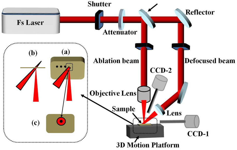
A schematic of the experimental setup is shown as Fig. 1. The laser source is a Ti:sapphire laser regenerative amplifier system with a central wavelength of 800 nm, pulse duration of 120 fs, and repetition rate of 1 kHz. The beam size was about 6 mm, controlled by an aperture. The electromechanical shutter was used to control the pulse numbers, and the laser energy incident on the sample was controlled by an attenuator, which was made up of a half-wave plate and a linear polarizer. The beam was first split by a 5/5 spectroscope, and then one of them was focused with a lens () on the sample surface. The other one was focused with a lens with a focal length of 200 mm behind the sample with a distance of 0.5 mm. The stainless alloy samples of a 0.5 mm thickness were amounted on a computer-controlled three-axis translation stage. The specific situation is shown in Figs. 1(a)–1(c). In order to ensure that the position of the two beams on the sample is the same, two CCD cameras were used for clearly online observation. CCD-1 is used to observe the distance of the beam spot from the samples; CCD-2 is used to check coincidence of the two beam spots and to observe the processing situation of the sample, as shown in Fig. 1. After irradiation, the sample was observed by Axio LSM700 laser confocal microscopy (LCM, Zeiss, Germany) and an SEM.
Sign up for Chinese Optics Letters TOC. Get the latest issue of Chinese Optics Letters delivered right to you!Sign up now

Figure 1.Schematic diagram of the laser irradiation system.
First, the basic impact of defocused irradiation time was investigated; Fig. 2 exhibits the ablation hole drilled by the fs laser with laser power of 6 mW at various defocused irradiation times. The number of the pulses used was 60. It is found that the width and the depth of the holes increase by 33% and 100%, respectively, without defocused irradiation and with defocused irradiation times of 15 and 30 min. The main mechanism is that after the defocused irradiation, the free electrons inside the metal are heated, and the electrons become very active, but the energy is not enough to help them achieve the band gap transition. It is well known that the optical absorption property of metal highly depends on the number of acoustic phonons, which has a certain function of temperature[32]. With the ablation beam coming, the defocused irradiation provided an extra temperature, and there are more acoustic phonons. Therefore, it is mostly a possibility that more electrons can achieve the transition, and more energy is absorbed. During the fabrication processing, the defocused light can confine the plasma around the center region, which will result in the temperature of the central plasma increasing. That will lead to more energy depositing on the stainless surface and the changes of the nanostructure morphology[8]. The reason for the change in diameter direction being smaller than depth direction is because the irradiation is along the beam propagation direction, so the depth direction has a greater impact. Figure 2 shows that as the defocused irradiation time increased, the affected area also increased, which is caused by the aforementioned effects.
Figure 2.LCM images of the hole drilled by the fs laser with different defocused irradiation times. (a) 0 min; (b) 15 min; (c) 30 min.
In order to comprehensively compare the ablation difference on the stainless alloy surface, a lot of experiments were conducted with different defocused irradiation times, as shown in Fig. 3. Figure 3 compares the geometry of the laser drilling hole with and without the defocused irradiation at various pulse numbers as a function of the irradiation time. The average for each point was determined using ten measured data with a standard deviation. As can be seen from the Fig. 3, the depth and the width of the hole both increases as the irradiation time increases before it becomes less than 30 min. After that the hole’s geometry changes little, the reason is that as the irradiation time increased, the affected area increased, but it cannot increase indefinitely. So, the maximum value of the affected area is obtained when the irradiation time is about 30 min under such experimental conditions. Also, by the contrast of the increment of the hole’s width and depth, it is found that the high-aspect ratio holes are achievable through this method. It is worth talking about the laser power of defocused light that is used here is 150 mW, and the defocused distance is 0.5 mm. So, the maximum ablation efficiency is achieved when the irradiation time is 30 min. If any of the parameters are changed, the time will change.
Figure 3.(Color online) Holes geometry as a function of defocused irradiation time at average laser power of 6 mW: (a) the LCM images; (b) the depth; (c) the width (diameter).
As the irradiation time and pulse number increased, the laser-induced periodic surface structures (LIPSSs) also show different shapes. Figure 4 shows the SEM with (15 min) and without the defocused irradiation at various pulse numbers. Because the higher temperature is caused by the pretreatment effect and the confined plasma plume, the LIPSSs become more irregular than the LIPSSs without the defocusing. It can be seen that as the pulse number increased because more energy was absorbed, the LIPSS became deeper, and the period became larger; Fig. 5 shows the SEM images of the LIPSS on the stainless alloy surface following 20 laser pulse ablations at a fluence of 3 μJ with different defocused irradiation times. According to the SEM images, it can be seen that the LIPSS exhibits different shapes as the irradiation time increased. Without the defocused irradiation, the LIPSSs were a regular structure, and the volume of those nanostructures covered on the LIPSSs surface is essentially less than 50 nm. As time increased, the LIPSSs become unshaped, as if it was roasted by a fire. This can be explained by the above analysis of the mechanism for this method. The pretreatment has caused the temperature of the irradiation area to rise, and in the subsequent ablation process, the large concentration of plasma makes the temperature improve further and ultimately lead to changes in its microstructure.
Figure 4.SEM images with (15 min) and without the defocused irradiation at various pulse numbers.
Figure 5.SEM images of LIPSS on the stainless alloy surface following 20 laser pulse ablations at a fluence of 3 μJ with different defocused irradiation times: (a) 0 min; (b) partial enlarged view of (a); (c) 15 min; (d) partial enlarged view of (d); (e) 30 min; (f) partial enlarged view of (e).
In order to demonstrate the capability of this method to fabricate other structures, the microchannels were fabricated, as shown in Fig. 6. For the microchannels, due to the defocused irradiation (30 min), the depth of the microchannels increased about 23%. Figure 6 also shows that compared with the microchannels fabricated without the irradiation, the heat affected an area enlarged by 100%, owing to the pretreatment effect and the confined plasma plume. Compared with the drilling holes, the depth increment is smaller, which is because the microchannels generally need to be processed for a certain length. So, we need to set the defocused irradiation scanning back and forth automatically, since the time of exposure per unit area is actually less than 30 min.
Figure 6.LCM images of the microchannels fabricated (c) with and (b) without defocused irradiation.
In conclusion, by using the defocused irradiation assisted technique, high ablation efficiency is experimentally demonstrated. The possible reason for this phenomenon is that the defocused irradiation will pretreat the sample material and transfer some energy to the electrons, making the electrons easily achieve band gap transition. Also, during the fabrication processing, the defocused irradiation can confine the plasma plume into the ablation areas, making the central plasma’s temperature increase, which will result in more energy deposited on the stainless surface. The SEM images indicate that as the irradiation time increases, the LIPSSs become messy, as if they were melted at a high temperature. Experimental results show that the maximum ablation efficiency can be achieved when the irradiation time is about 30 min. Compared with the traditional indicated processing, the ablation efficiency is increased by almost three times. This method also can fabricate other function structures, like microchannels, high-aspect ratio holes, etc.
References
[1] K. Yin, Y. X. Song, X. R. Dong, C. Wang, J. A. Duan. Sci. Rep., 6, 36557(2016).
[2] K. Yin, X. R. Dong, F. Zhang, C. Wang, J. A. Duan. Appl. Phys. Lett., 110, 121909(2017).
[3] L. Yang, S. Y. Ji, K. N. Xie, W. Q. Du, B. J. Liu, Y. L. Hu, J. W. Li, G. Zhao, D. Wu, W. H. Huang, S. L. Liu, H. Y. Jiang, J. R. Chu. Opt. Express, 25, 8144(2017).
[4] Y. Lu, L. D. Yu, Z. Zhang, S. Z. Wu, G. Q. Li, P. C. Wu, Y. L. Hu, J. W. Li, D. Wu. RSC Adv., 7, 11170(2017).
[5] X. Dong, Z. Xie, Y. Song, K. Yin, D. Chu, J. Duan. Chin. Opt. Lett., 15, 071403(2017).
[6] K. Yin, J. A. Duan, X. Y. Sun, C. Wang, Z. Luo. Appl. Phys. A, 119, 69(2015).
[7] L. Wang, B. B. Xu, Q. D. Chen, Z. C. Ma, R. Zhang, Q. X. Liu, H. B. Sun. Opt. Lett., 36, 3305(2011).
[8] X. H. Li, K. H. Hu, B. Lyu, J. D. Zhang, Y. W. Wang, P. Wang, S. Xiao, Y. L. Gao, J. He. J. Phys. Chem. C, 120, 18243(2016).
[9] L. Wang, Q. D. Chen, R. Yang, B. B. Xu, H. Y. Wang, H. Yang, C. S. Huo, H. B. Sun, H. L. Tu. Appl. Phys. Lett., 104, 031904(2014).
[10] S. Nolte, C. Momma, H. Jacobs, A. Tunnermann, B. Chichkov, B. Wellegehausen, H. Welling. J. Opt. Soc. Am. B, 14, 2716(1997).
[11] D. Ashkenasi, M. Lorenz, R. Stoian, A. Rosenfeld. Appl. Surf. Sci., 150, 101(1999).
[12] A. Weck, T. Crawford, D. Wilkinson, H. Haugen, J. Preston. Appl. Phys. A, 90, 537(2008).
[13] S. Besner, J. Y. Degorce, A. Kabashin, M. Meunier. Appl. Surf. Sci., 247, 163(2005).
[14] Y. Hu, H. Yue, J. Duan, C. Wang, J. Zhou, Y. Lu, K. Yin, X. Dong, W. Su, X. Sun. Chin. Opt. Lett., 15, 021404(2017).
[15] K. Yin, J. A. Duan, C. Wang, X. R. Dong, Y. X. Song, Z. Luo. Appl. Phys. Lett., 108, 241601(2016).
[16] U. Chakravarty, P. Naik, C. Mukherjee, S. Kumbhare, P. Gupta. J. Appl. Phys., 108, 053107(2010).
[17] D. Chu, X. Sun, Y. Hu, X. Dong, K. Yin, Z. Luo, J. Zhou, C. Wang, J. Duan. Chin. Opt. Lett., 15, 071403(2017).
[18] K. Sugioka, M. Iida, H. Takai, K. Micorikawa. Opt. Lett., 36, 2734(2011).
[19] M. Fang, S. Baldelli. J. Phys. Chem. C., 121, 1591(2017).
[20] M. Fang, S. Baldelli. J. Phys. Chem. Lett., 6, 1454(2015).
[21] S. Guizard, P. D’Oliveira, P. Daguzan, P. Marthn, P. Meynadier, G. Petite. Nucl. Instrum. Methods Phys. Res. B, 116, 43(1996).
[22] A. Y. Vorobyev, V. S. Makin, C. L. Guo. Phys. Rev. Lett., 102, 234301(2009).
[23] T. H. Her, R. J. Finlay, C. Wu, S. Deliwala, E. Mazur. Appl. Phys. Lett., 73, 1673(1998).
[24] Y. C. Guan, G. K. L. Ng, H. Y. Zheng, M. H. Hong, X. Hong, Z. Zhang. Appl. Surf. Sci., 270, 526(2013).
[25] L. Liu, S. Li, X. N. He, X. Huang, C. F. Zhang, L. S. Fan, M. X. Wang, Y. S. Zhou, K. Chen, L. Jiang, J. F. Silvain, Y. F. Lu. Opt. Express, 22, 7686(2014).
[26] Q. X. Wang, A. M. Chen, S. Y. Li, H. X. Qi, Y. Qi, Z. Hu, M. X. Jin. Appl. Opt., 54, 8235(2015).
[27] L. Liu, X. Huang, S. Li, Y. Lu, K. Chen, L. Jiang, J. F. Silvain, Y. F. Lu. Opt. Express, 23, 015047(2015).
[28] G. L. Deng, G. Y. Feng, K. Liu, S. H. Zhou. Appl. Opt., 53, 3004(2010).
[29] R. C. Reed. The Super Alloys: Fundamentals and Applications(2006).
[30] M. J. Wahll, D. J. Maykuth, H. J. Hucek. Handbook of Superalloys(1979).
[31] S. Baik, M. J. Olszta, S. M. Bruemmer, D. N. Seidman. Scr. Mater., 66, 809(2012).
[32] L. S. Jiao, S. K. Moom, E. Y. K. Ng, H. Y. Zheng, H. S. Son. Appl. Phys. Lett., 104, 181902(2014).