Abstract
Wepresent a novel method for engineering ultra-flattened-dispersion photonic crystal fibers with uniform air holes by rotations of inner air-hole rings around the fiber core. By choosing suitable rotation angles of each inner ring, theoretical results show that normal, anomalous, and nearly zero ultra-flattened-dispersion fibers in wide spectra ranges of interest can be obtained alternatively. Moreover, in our dispersion sensitive analysis, these types of fibers are robust to variations from optimal design parameters. The method is suitable for the accurate adjustment of fiber dispersion within a small range, which would be valuable for the fabrication of ultra-flattened-dispersion fibers and also have potential applications in wide-band high-speed optical communication systems.1. INTRODUCTION
In high-speed optical communication systems, fiber dispersion is a crucial factor that has great influence on the bandwidth of information transmission. Conventionally, in order to decrease the dispersion effect, dispersion-shifted fiber and zero-dispersion single-mode fiber are designed for communication wavelengths. In recent years, photonic crystal fiber (PCF) [1], has became a preeminent method for transmitting information because of its unique optical properties and flexible designs. The variety of possible geometries in PCF offers great possibility to control its dispersion properties, particularly useful in designing dispersion flattened fibers over a wide range of wavelengths.
Over the last decade, various PCFs have been proposed and studied to obtain ultra-flattened-dispersion property. Initially, characterized by the lattice constant and hole diameter, relative flattened dispersion can be achieved [2,3]. After that, in order to improve dispersion flatness over a wider bandwidth, more complicated design methods have been exploited, such as doping additional materials such as in the central part of the silica core [4,5], changing the diameter of the air holes belonging to the first two or three inner rings [6,7], modifying the circular air holes into other shapes [8–10], selectively filling the PCF with liquids [11], designing a hybrid core region with three-fold symmetry for the fiber [12], assembling additional defected air holes in the central core region [13], or combining two or more of these methods, for instance, introducing both -or F-doped silica and also modifying the circular holes into hollow rings in the PCFs [14]. While wonderful dispersion flatness performance could be obtained, the modifications either broke the uniformity of the holes’ size or introduced additional materials, which will raise complexity during the design of fibers. In addition, minor variations of these design parameters that would be introduced in the fabrication process are likely to cause a large change of the dispersion characteristic. Therefore, the realization of ultra-flattened-dispersion PCFs with low sensitivity by a relatively simple method is still a challenge.
In this paper, we propose a novel design approach for achieving ultra-flattened-dispersion PCFs over wide wavelength regions with low sensitivity just by rotations of two inner air-hole rings around the fiber core. The approach can obtain ultra-flattened-dispersion PCFs while maintaining the uniformity of the PCFs’ air-hole size. Numerical results show that our proposed method for control of dispersion in PCFs works well. The paper is organized as follows. In Section 2, the topology and design principle of proposed PCFs are presented. Then, in Section 3, dispersion engineering for nearly zero-dispersion PCFs, normal dispersion PCFs, and abnormal dispersion PCFs is investigated in detail. In Section 4, a sensitive analysis is performed to determine the variations of the dispersion characteristic arising from inevitable imprecision angles of the inner rings. Finally, conclusions are given in Section 5.
Sign up for Photonics Research TOC. Get the latest issue of Photonics Research delivered right to you!Sign up now
2. SCHEMATIC TOPOLOGY AND DESIGN PRINCIPLE
The schematic cross section of the proposed PCF topology structure is depicted in Fig. 1. The host material is pure silica, and the number of air-hole rings is assumed to be 11. It is composed of circular air holes arranged in a triangular array of lattice constant with the central air hole missing, and all air holes have a uniform diameter . As denoted in the right panel of Fig. 1, the central core area of the fiber is additionally modified by rotations of the innermost two air-hole rings around the fiber core with angles of degrees and degrees relative to their original positions to obtain ultra-flattened dispersion, respectively. And the original positions of air holes in the inner two rings are also denoted in the right panel of Fig. 1 as dashed circles.
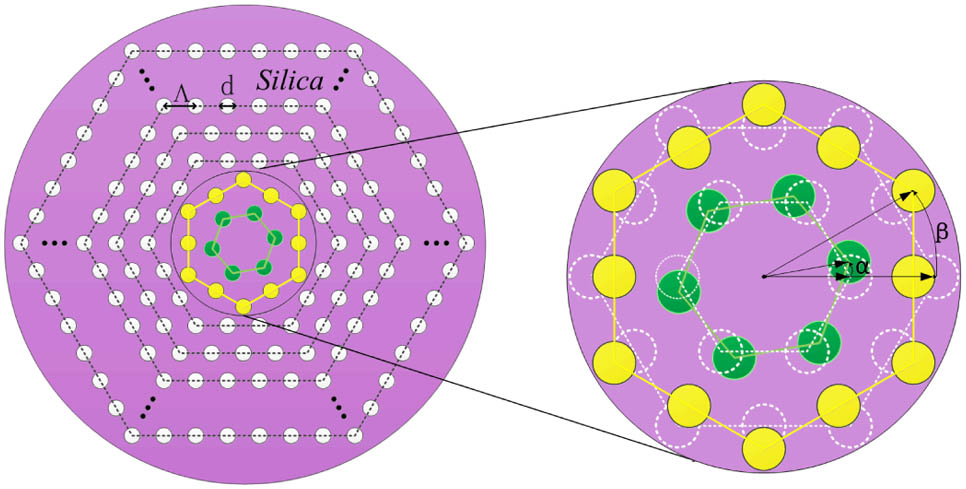
Figure 1.Schematic topology of the proposed PCFs structure. The air holes in the silica background are arranged in a triangular configuration of lattice constant with the central air hole missing, and all air holes have a uniform diameter . The first and second innermost air-hole rings (colored green and yellow, respectively) are rotated around the fiber core with angles of degrees and degrees relative to their original positions, respectively. And the original positions of air holes in the inner rings are denoted as dashed circles in the right panel.
It is clear that there are four structure parameters, namely , , , and , which can be tuned to achieve the ultra-flattened-dispersion PCFs. Hence, our design strategy is performed in two steps. First, relatively dispersion flattened PCFs are obtained by varying parameters and [3]. Then, we try to tailor the dispersion of PCFs further by carefully adjusting both and . A plane-wave expansion method with a lattice resolution of 32 is employed to obtain highly accurate dispersion values of the fundamental mode of fibers in the numerical calculations [15]. And the material dispersion is directly included in the calculations through the Sellmeier equation. In order to get a highly accurate result, a minimum change step of 1° is adopted near the optimum structure parameters.
3. DISPERSION ENGINEERING AND ANALYSIS
In this section, we will show how to realize nearly zero-dispersion ultra-flattened PCF, normal dispersion ultra-flattened PCF, and anomalous dispersion ultra-flattened PCF through dispersion engineering by our proposed topology. We start from the achievement of nearly zero-dispersion ultra-flattened PCF. As mentioned in Section 2, first, relatively flattened zero-dispersion PCF is obtained by choosing appropriate parameters and . We know the total dispersion is approximately equal to the sum of the geometrical dispersion and material dispersion , that is, , and the slope of the curve being fixed. Through performing a scaled curve having a liner resign with the same slope as , and meanwhile ensuring the wavelength region where behaves linearly overlaps the wavelength region of linear behavior of , we will obtain an ultra-flattened-dispersion curve in the overlapping wavelength range. Reference [3] has given the results that, by fixing and changing , the curve of is shifted, and the slope of its linear part is modified. Meanwhile, by fixing and changing the curve of is shifted, but the slope of its linear part is approximately preserved. According to the above conclusion, coupled with a further calculation, and are chosen. Second, dispersion is further optimized by engineering the parameters and . Thus, the influence exerted by parameters and on the dispersion characteristic should be investigated in detail.
Before optimizing, the tuning ranges of and should be determined first. Due to the geometric symmetry of the proposed PCF structure, if we only take one of the parameters and as the variation parameter and fix the other, a variation range with a minimum period of 30° should be enough to represent all the cases of angle variations. For example, when is fixed with 0°, variation of within 0° to 30° is enough. However, if we take and simultaneously as tuning factors, an angle variation range of 60° should be required. Specifically, when one of the parameters has a symmetric angle, it is equal to the case of variation of only one parameter. Thus, an angle variation range for the other parameter of 30° would be enough for one of the parameters maintained at the symmetric angle. For example, when is 30°, variation of within 0° to 30° is also enough.
Figure 2 plots the chromatic dispersion as a function of the wavelength . Figure 2(a) shows the chromatic dispersion dependence on the change of parameter , while is fixed with original degree. And Fig. 2(b) shows the chromatic dispersion dependence on the change of parameter , while is fixed. From Fig. 2, it is evident that when increasing or separately from 0° to 30°, the curves all shift upward. So variation of or will lead to a similar dispersion changing tendency. And as the curve shifts upward, the chromatic dispersion curve becomes flatter since the peak at shorter wavelength increases slower than the valley rising at longer wavelength.

Figure 2.Chromatic dispersion as a function of wavelength with and for changing one of the design parameters: (a) is changing from 0° to 30°, while is fixed, and (b) is changing from 0° to 30°, while is fixed.
Comparing Figs. 2(a) and 2(b), while the impact of on the chromatic dispersion in the long wavelength zone is much greater than that of , the impact of on the dispersion in the short wavelength zone is less sensitive. The reason can be explained as follows. Since the innermost ring is much nearer to the fiber central core than the second innermost ring, the short wavelengths at first can only have a serious influence on the innermost ring, and they have less influence on the second innermost ring. As wavelength increases, the light can penetrate the first innermost ring and could have a direct influence on the second innermost ring too. So variation of the second innermost ring will heavily affect the optical properties of fiber in the long wavelength zone. As shown in Fig. 3, it also can be explained by the transverse electric field intensity distributions of the fundamental mode for both short wavelength and long wavelength. Figure 3(a) shows the transverse electric field intensity distribution of the fundamental mode at 1.45 μm for the original PCF, which is with both and equal to 0°, and Figs. 3(b) and 3(c) show the electric field intensity distributions at the same wavelength for the maximum variations of and , respectively. Correspondingly, Figs. 3(d), 3(e), and 3(f) show the electric field intensity distributions at 1.75 μm wavelength for these three structure cases as in Figs. 3(a), 3(b), and 3(c). As wavelength increases, it is clear that variation of the second innermost ring leads to more mode-field distribution penetrating to the cladding compared to the variation of the first inner ring. Thus, the chromatic dispersion is very sensitive to . Therefore we first use for a coarse tuning; then, we fix with a relative optimized value and use for an accurate tuning to obtain wide-band ultra-flattened nearly zero dispersion. Here, we focus on the chromatic dispersion curve with the lowest fluctuation for a wavelength range from 1.25 to 1.65 μm. As shown in Fig. 2(b), through a preliminary engineering, is selected as the parameter for the proposed nearly zero-dispersion flattened PCF.
Figure 3.Fundamental mode transverse electric field intensity () distributions at 1.45 μm (upper figures) and 1.75 μm (lower figures) wavelengths, for nearly zero-dispersion flattened PCFs with and for (a) and , (b) and , (c) and , (d) and , (e) and , and (f) and .
Then we investigate the combined influence of and for a final optimization of nearly zero-dispersion fiber. Figure 4 shows the variations of the chromatic dispersion versus wavelength for changing from 0° to 59° with optimized . While increasing from 0° to 20°, the dispersion curve shifts down first and gets the lowest at 20°. Continuously increasing from 20° to 50°, the dispersion curve tends to rise up and gets the highest at 50°. Finally, increasing from 50° to 59°, the dispersion curve tends to shift downward again and gets close to its original position. This can be explained as follows. As increases from 0° with a fixed , the difference between and , i.e., , first tends to be smaller, and thus its variation on dispersion becomes weaker, so the dispersion curve shifts downward before reaches 20°. On the contrary, once gets bigger again, its variation on dispersion becomes stronger again, so the dispersion curve shifts upward again and gets to the highest extreme at with 50°, which is equal to the maximum of 30°. Finally, the optimum dispersion curve can be obtained with and , and its dispersion variations are within in a wavelength range of 1.25–1.65 μm. So we can see that the flatness of dispersion is finely tuned by adjusting parameters and .
Figure 4.Chromatic dispersion as a function of wavelength with and for changing from 0° to 59°, while has an optimized value of 20°.
After the design of nearly zero ultra-flattened-dispersion PCF, normal ultra-flattened-dispersion PCF and anomalous ultra-flattened-dispersion PCF are also proposed. The suitable lattice constant and hole diameter have also been chosen for them, which have the values of , and , , respectively. The method we used to choose these parameters for the normal flattened-dispersion PCF and anomalous flattened-dispersion PCF is the same as that for zero ultra-flattened-dispersion PCF. Then based on previous experience deduced from the design of zero ultra-flattened-dispersion PCF, the optimum normal and anomalous ultra-flattened-dispersion curves are all easily achieved.
In Fig. 5, we show the calculated chromatic dispersion for changing or while reserving the other parameters. In the figure, the black solid curve represents the chromatic dispersion of the initial fiber with and . The blue solid curves with various geometric shapes show the chromatic dispersion dependence on the changing , while is unchanged. The red dashed-dotted curves with various geometric shapes describe the chromatic dispersion dependence on the changing parameters , while is unchanged. The impact of structure parameters changing on chromatic dispersion shown in Fig. 5(b) is similar to what we have shown in Fig. 2. Parameter has much greater influence on the chromatic dispersion than does in the long wavelength zone, while in the short wavelength zone, has comparable impact on the dispersion compared with . However, for Fig. 5(a), the situation changes much. For the short wavelength zone, in spite of changing and , the chromatic dispersion is changed minimally. And when the wavelength is beyond a specific value, the dispersion curve becomes sensitive to the structure parameters. First, it is much more sensitive to the changing of the innermost ring. And as the wavelength increases to the long wavelength zone, the second innermost ring also plays an important role in controlling the fiber dispersion. The phenomena can be understood similar to what we explained for the nearly zero-dispersion PCF in the previous part. The different sensitivities found in these figures would mainly arise from the different period , which we have chosen to obtain different kinds of chromatic dispersion behaviors. For Figs. 2 and 5(b), their periods are 2.3 and 2.2 μm, respectively. So, the dispersion behavior shown in these figures is similar. However, for Fig. 5(a), a large period of 2.7 μm is adopted. Therefore, only longer wavelengths are sensitive to the change of and .
Figure 5.Chromatic dispersion as a function of the wavelength , for changing structure parameters or from 0° to 30° while reserving the other parameters, for (a) normal ultra-flattened-dispersion PCF with and , and (b) abnormal ultra-flattened-dispersion PCF with and .
From the results shown in Fig. 5(a), is selected as the preliminary parameter for the proposed normal dispersion flattened PCF in a wavelength range of 1.5–2.0 μm. While from the curves shown in Fig. 5(b), is selected as the preliminary parameter for the proposed anomalous dispersion flattened PCF in a wavelength range of 1.25–1.65 μm.
After that, a final optimizing process for normal ultra-flattened-dispersion PCF and anomalous ultra-flattened-dispersion PCF is also shown in Figs. 6(a) and 6(b). We note that when increases from 0° to 59°, the curves changing tendency shown in Figs. 6(a) and 6(b) are similar to what we have shown in Fig. 4. In the end, the optimum parameters of and are selected for the normal ultra-flattened-dispersion PCF, and its corresponding dispersion variations are within in the wavelength range of 1.5–2.0 μm. Also, the optimum parameters of and are selected for the anomalous ultra-flattened-dispersion PCF, and its corresponding dispersion variations are in the wavelength range of 1.25–1.65 μm.
Figure 6.Chromatic dispersion as a function of the wavelength , for the changing (a) normal ultra-flattened-dispersion PCF with , , and , and (b) abnormal ultra-flattened-dispersion PCF with , , and .
4. SENSITIVE ANALYSIS
In the previous sections, various kinds of ultra-flattened-dispersion PCFs with uniform air holes have been theoretically realized by rotations of inner two air-hole rings around the core with specific angles. But considering the inevitable imprecision that would be introduced during the fabrication process, it may affect the dispersion characteristics of the proposed PCFs. Thus, sensitive analysis regarding the impact of the fluctuation of the design parameters on the dispersion characteristics should be performed.
Due to the fact that the PCFs can be fabricated with high lattice uniformity and with high precision to the cladding hole diameter [13,16], we only focus our sensitive analysis on the air-hole positions of the inner two rings due to inaccurate angles of the rings. Here, taking the ultra-flattened zero-dispersion PCF for example, a set of calculations is performed to show the impact of variation of or on the chromatic dispersion, in which either or or and is deviated , from the optimum point and . As plotted in Fig. 7, we note even in the extreme condition that deviated 3° and has the inverse change; the maximum variation of dispersion is still within around the nominal dispersion value. In fact, according to the fabrication date in Ref. [16], the extreme situation will not be likely to occur in our cases. As a result, we can draw a conclusion that possible variations of the design parameters of the proposed fibers will not influence the dispersion property much.
Figure 7.Chromatic dispersion as a function of the wavelength with and ; or/ and are varied from their optimum values of and .
Further research is also carried out to figure out why the fiber is not sensitive to fluctuations of the optimum design parameters. The impact of variations of optimum parameters and on the effective mode area of the fundamental mode is calculated and analyzed. The design parameters that we choose are the same as in Fig. 7, and their corresponding effective mode areas at the wavelength of 1.55 μm are given in Table 1. It is easy to find the correspondence between the effective mode area and the chromatic dispersion curve. As the effective mode area increases, the chromatic dispersion shifts up. The largest variation of effective mode area and the largest variation of dispersion have the same parameters. And even in the worst condition, the maximum variation of effective mode area to the nominal value is only . Therefore, it is easy to say that the fiber is not sensitive to fluctuations of its optimum design parameters. Thus, our proposed fiber is a robust design.
| α[°] | β[°] | Aeff[μm2] |
|---|
| 0 | 20 | 31.7186 |
| 0+0 | 20+3 | 31.8863 |
| 0+0 | 20−3 | 31.3310 |
| 0+3 | 20+0 | 31.5597 |
| 0−3 | 20+0 | 31.8842 |
| 0+3 | 20−3 | 31.1745 |
| 0−3 | 20+3 | 32.0136 |
| 0+3 | 20+3 | 31.7454 |
| 0−3 | 20−3 | 31.5134 |
Table 1. Effective Mode Areas at for Different Parameters with and
5. CONCLUSIONS
In conclusion, we have demonstrated a novel method for realizing ultra-flattened-dispersion PCFs with uniform air holes by rotations of each inner air-hole ring wholly around the fiber core. It only uses four parameters, namely , , , and , to control the dispersion of PCFs. and take charge of the regulation of dispersion in a wide range, while and are responsible for the accurate adjustment of dispersion in a small range. Theoretical results show that nearly zero, normal, and anomalous ultra-flattened-dispersion fibers in wide spectra ranges of interest all can be obtained. These proposed fibers reduce the difficulty of designs compared to that with multiple different submicrometer air-hole sizes or introduce other kinds of materials. Sensitive analysis also shows that possible fluctuation of design parameters will not affect the desired dispersion property seriously. Moreover, this method can work as a companion for the existing dispersion tailoring technologies to accurately adjust dispersion within a small range. Thus, we believe our proposed fiber structure is a robust design, which would have potential applications in wide-band high-speed optical communication systems.
References
[1] J. C. Knight, T. A. Birks, P. St. J. Russell, D. M. Atkin. All-sillca single-mode optical fiber with photonic crystal cladding. Opt. Lett., 21, 1547-1549(1996).
[2] A. Ferrando, E. Silvestre, J. J. Miret, P. Andrés. Nearly zero ultraflattened dispersion in photonic crystal fibers. Opt. Lett., 25, 790-792(2000).
[3] A. Ferrando, E. Silvestre, P. Andres, J. J. Miret, M. V. Andrés. Designing the properties of dispersion-flattened photonic crystal fibers. Opt. Express, 9, 687-697(2001).
[4] Y. L. Hoo, W. Jin, J. Ju, H. L. Ho, D. N. Wang. Design of photonic crystal fibers with ultra-low, ultra-flattened chromatic dispersion. Opt. Commun., 242, 327-332(2004).
[5] S. Lou, H. Fang, H. Li, T. Guo, L. Yao, L. Wang, W. Chen, S. Jian. Design of broadband nearly-zero flattened dispersion highly nonlinear photonic crystal fiber. Chin. Opt. Lett., 6, 821-823(2008).
[6] T. L. Wu, C. H. Chao. A novel ultraflattened dispersion photonic crystal fiber. IEEE Photon. Technol. Lett., 17, 67-69(2005).
[7] F. Poli, A. Cucinotta, S. Selleri, A. H. Bouk. Tailoring of flattened dispersion in highly nonlinear photonic crystal fibers. IEEE Photon. Technol. Lett., 16, 1065-1067(2004).
[8] J. Wang, C. Jiang, W. Hu, M. Gao. Modified design of photonic crystal fibers with flattened dispersion. Opt. Laser Technol., 38, 169-172(2006).
[9] S. E. Kim, B. H. Kim, C. G. Lee, S. Lee, K. Oh, C.-S. Kee. Elliptical defected core photonic crystal fiber with high birefringence and negative flattened dispersion. Opt. Express, 20, 1385-1391(2012).
[10] N. H. Hai, Y. Namihira, S. F. Kaijage, T. Kinjo, F. Begum, S. M. A. Razzak, N. Zou. A unique approach in ultra-flattened dispersion photonic crystal fibers containing elliptical air-holes. Opt. Rev., 15, 91-96(2008).
[11] K. M. Gundu, M. Kolesik, J. V. Moloney, K. S. Lee. Ultra-flattened-dispersion selectively liquid-filled photonic crystal fibers. Opt. Express, 14, 6870-6878(2006).
[12] K. P. Hansen. Dispersion flattened hybrid-core nonlinear photonic crystal fiber. Opt. Express, 11, 1503-1509(2003).
[13] N. Florous, K. Saitoh, M. Koshiba. The role of artificial defects for engineering large effective mode area, flat chromatic dispersion, and low leakage losses in photonic crystal fibers: towards high speed reconfigurable transmission platforms. Opt. Express, 14, 901-913(2006).
[14] J. Park, S. Lee, S. Lee, S. E. Kim, K. Oh. Dispersion control in square lattice photonic crystal fiber using hollow ring defects. Opt. Express, 20, 5281-5290(2012).
[15] S. Guo, S. Albin. Simple plane wave implementation for photonic crystal calculations. Opt. Express, 11, 167-175(2003).
[16] F. Poletti, V. Finazzi, T. M. Monro, N. G. R. Broderick, V. Tse, D. J. Richardson. Inverse design and fabrication tolerances of ultra-flattened dispersion holey fibers. Opt. Express, 13, 3728-3736(2005).


