
Jin Li, Yanbo Dou, Lixin Wang, Jinhai Zou, Yu Ding, Hang Wang, Qiujun Ruan, Zhipeng Dong, Zhengqian Luo. New ultrashort pulsewidth measurement technology based on interference jitter and FPGA platform[J]. Chinese Optics Letters, 2022, 20(3): 031404
- Chinese Optics Letters
- Vol. 20, Issue 3, 031404 (2022)
Abstract
1. Introduction
Ultrafast lasers are widely used in many fields, such as biomedicine[
In 1967, the intensity autocorrelation (AC) theory was proposed[
In this Letter, we propose and demonstrate an all-fiber pulsewidth measurement technology based on the interference jitter (IJ) and field-programmable gate array (FPGA) platform, which does not require nonlinear crystals or a TPA detector and shows a compact/intelligent capability. The measured spectral range can cover the range from the near-infrared to mid-infrared, and the measured pulsewidth can be from tens of femtoseconds (fs) to 100 ps. This technology represents a new paradigm of pulsewidth measurement setup with the advantages of compactness, high performance, and ease of use.
Sign up for Chinese Optics Letters TOC. Get the latest issue of Chinese Optics Letters delivered right to you!Sign up now
2. Operation Principle and Experimental Setup
2.1. Design and setup
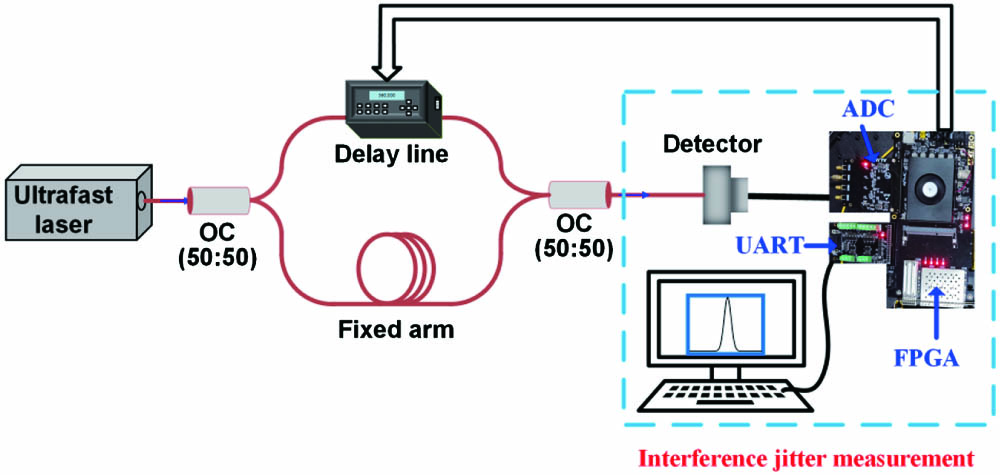
Figure 1 shows the schematic design of our proposed pulsewidth measurement technology based on IJ-FPGA. The measurement setup is mainly composed of an interference part and an IJ data acquisition and processing system. The interference part consists of two 50/50 optical couplers (OCs), a fixed arm with a section of matching fiber, and a fiber delay line (MDL-002, General Photonics, Inc.). The delay line is set to 0 ps position at absolute origin, and the delay range can be from 0 to 560 ps, which determines the maximum pulse width measured up to . The optical delay resolution is 1 fs, and the optical delay accuracy is , implying that the narrowest measurable pulsewidth is tens of fs. The IJ data processing system mainly realizes fast and accurate acquisition and recording of IJ signals at different delay (see Section 2.2). The system mainly includes the low-speed photodetector (PD), carrier card, and factor card. The InGaAs amplified PD (Thorlabs, PDA05CF2) with a 150 MHz bandwidth is used to measure the wavelength of 800–1700 nm, and the noise equivalent power (NEP) is . In the 2 µm band, there is a 12.5 GHz PD (Electro-Optics Technology, Inc., ET-5000F). The carrier card chooses the FPGA development board, and the factor card includes an analog-to-digital conversion (ADC) module and universal asynchronous receiver/transmitter (UART) transmission module. The ADC module realizes the conversion of the analog signal output stemming from the PD to the digital signal. The module has a sampling frequency of 125 MS/s, a digital bit width of 12 bits, and an input voltage range of . The sampling frequency limits the repetition frequency of the signal source to be below 62.5 MHz, based on the Nyquist sampling theorem. In our experiment, the IJ signal generally appears within 10 s after the delay-line set, so the FPGA carrier card mainly realizes the storage and maximum value detection of the digital signals collected within 10 s. The UART module realizes the transmission of maximum value data to the personal computer (PC) with the transmission baud rate of 9600. Since the method is a statistical detection method, it should be pointed out that our measurement method may only apply to the case of higher repetition rate [i.e., above the megahertz (MHz) level].
![]()
Figure 1.Schematic of the all-fiber pulsewidth measurement setup based on IJ-FPGA.
2.2. Operation principle
According to the IJ-FPGA setup in Fig. 1, the ultrafast laser to be measured is divided into two arms, in which the delay time of one arm is variable, and the delay time of the other arm is fixed. The optical fields of the variable arm and the fixed arm interfere at the output port. After superposition, the optical field can be expressed as
![]()
Figure 2.(a) Pulses of the fixed arm and the variable arm at different delay times τ, (b) the pulse envelope measured by a low-speed PD at the corresponding delay time τ, and (c) the normalized Vmax data (blue dots) and fitting envelope (red line).
![]()
Figure 3.Intensity envelope of the original pulse (red line) and the numerically simulated (τ, Vmax) envelope (blue line) in (a) the fs regime and (b) the ps regime.
3. Result and Discussion
3.1. Broadband pulsewidth measurement
First, we used the IJ-FPGA setup (see Fig. 1) to measure 1.06 µm ultrashort pulses, which are from a home-made, SESAM mode-locked Yb-doped polarization-maintaining fiber laser, as shown in Fig. 4(a). The spectrum [Fig. 4(b)] of the mode-locked laser has a central wavelength of 1064.0 nm and a pulse repetition rate of 19.331 MHz. For comparison, the pulse width was measured by our IJ-FPGA technology and a commercial autocorrelator, respectively. In Fig. 4(c), the red dots were recorded by the IJ-FPGA setup with the input average power of 15 µW, and was measured to be 11.74 ps. Meanwhile, the blue curve was recorded by a commercial autocorrelator (Femtochrome Research, FR-103XL), and the . Considering the hyperbolic secant pulse, the pulse width is . The relative error between the two technologies is only 1.8%. To further confirm the wide measurement range of the IJ-FPGA technology, we also measured -level ultrashort pulses at 1.06 µm. The experimental setup of such -level 1.06 µm laser is similar to Fig. 4(a), except that a SESAM with different performance was used. The central wavelength of the ultrafast laser is 1063.1 nm, as shown in Fig. 4(d), and the pulse repetition rate is 18.601 MHz. When the input average power is 62 µW, in Fig. 4(e), the pulse widths measured by our IJ-FPGA setup and a commercial autocorrelator are 81.53 ps and 81.65 ps, respectively. The relative error is as low as 0.15%.
![]()
Figure 4.(a) Experimental setup of the 1.06 µm ultrafast laser. WDM, wavelength-division multiplexer; PM-YSF, polarization-maintaining Yb-doped fiber; CFBG, chirped fiber Bragg grating. (b) and (d) Optical spectra. (c) and (e) AC trace with a commercial autocorrelator (blue line) and IJ-FPGA trace (red dots).
Furthermore, to verify the broadband spectrum applicability of the IJ-FPGA technology, we used the setup to measure 1.5 µm and 2.15 µm ultrashort pulses as follows. Figure 5(a) is a homemade 1.5 µm CNT mode-locked polarization-maintaining Er-doped fiber laser, and the laser has a central wavelength of 1561.5 nm [see Fig. 5(b)] and a pulse repetition rate of 22.801 MHz. Figure 5(c) gives the pulsewidth measured result (red dots) by the IJ-FPGA setup with the input average power of 5 µW, and . The blue line in Fig. 5(c) was measured by the FR-103XL commercial autocorrelator, and the pulse width is 1.07 ps. The measured results of both technologies are in good agreement, and the relative error is 3.8%. Then, we also measured fs pulses at 1.58 µm (based on nonlinear spectral broadening). The central wavelength is 1582.4 nm with a 3 dB bandwidth of [see Fig. 5(d)] and a pulse repetition rate of 14.293 MHz. As shown in Fig. 5(d), when the input average power was 20 µW, the pulsewidth measured by our IJ-FPGA setup and the FR-103XL commercial autocorrelator is 412.9 fs and 412.1 fs, respectively. The experimental results well prove the reliability of the IJ-FPGA for measuring fs ultrashort pulses. However, it should be pointed out that the measurement accuracy will sharply worsen for pulsewidth, due to the nonlinearity and dispersion influence of fiber used in the IJ-FPGA setup on pulsewidth broadening or compression.
![]()
Figure 5.(a) Experimental setup of the 1.5 µm ultrashort pulsed laser. OC, optical coupler. (b) and (d) Optical spectra of the measured ultrafast laser. (c) and (e) AC trace with a commercial autocorrelator (blue line) and IJ-FPGA trace (red dots).
We further utilized the IJ-FPGA technology to measure an ultrafast laser operated at 2.15 µm. Figure 6(a) depicts a schematic of the 2.15 µm ultrafast laser based on Raman soliton self-frequency shift. As shown in Fig. 6(b), the 2153.0 nm ultrashort pulsed laser has a 3 dB bandwidth of 39.0 nm, and the pulse repetition rate is 35.305 MHz. In the Fig. 6(c), the red dots were recorded by the IJ-FPGA setup at the input power of 150 µW. By fitting, the pulsewidth was measured as , but the AC result for comparsion cannot be provided due to the inaccessibility of the FR-103XL autocorrelator at 2.15 µm.
![]()
Figure 6.(a) Schematic of the 2.15 µm ultrafast fiber laser. TDF, Tm3+-doped double-clad fiber. (b) Optical spectrum. (c) IJ-FPGA trace (red dots) and fitting (red line).
3.2. High-sensitivity pulsewidth measurement
In addition, to evaluate the measurement sensitivity of the IJ-FPGA technology, a tunable optical attenuator was inserted to the output end of a homemade 1.56 µm ultralfast laser to repeat the pulsewidth measurement with the different input average power. The pulse widths of the ultrafast laser with average input power of 10 µW, 500 µW, and 2 mW were measured by the IJ-FPGA setup, respectively. The results are shown in Fig. 7, and all of them are the same as 613.7 fs, confirming that the IJ-FPGA technology can be valid in a wide range [from microwatts (µW) to milliwatts (mW) at least] of input power and shows an excellent consistency in pulsewidth measurement.
![]()
Figure 7.IJ-FPGA trace (red dots) and fitting envelope (blue line) with different input power (pulse energy).
Last, we have calculated the average-power-peak-power product () and the measurable pulse energy in the 1.06–2.15 µm wavebands. A minimum pulse energy of 219 fJ is experimentally detected with of . Compared with the detected of the FR-103XL commercial autocorrelator (i.e., in our experiment), the minimum detectable of our IJ-FPGA setup is remarkably improved, i.e., a higher sensitivity. In fact, the sensitivity of the IJ-FPGA setup is limited by the large loss (3.98 dB at 1.5 µm and 6.99 dB at 1.06 µm) of the delay line used in our system. If the whole fiber system is fusion spliced instead of using fiber connectors, and a better delay line with low insertion loss is chosen, we estimate that the allowable single pulse energy can be , and the can be improved to (corresponding to an average power of dBm) in the 1.5 µm band. In the 1.06 µm band, the allowable single pulse energy can be estimated as , and the can be improved to (corresponding to an average power of ).
4. Conclusion
In summary, we have proposed and demonstrated a ultrafast laser pulsewidth measurement technology based on IJ-FPGA. This technology does not need nonlinear crystals or a TPA detector and shows a compact structure and intelligent capability. By using the IJ-FPGA technology, we have measured the pulsewidths of the ultrafast lasers at 1.06, 1.5, and 2.15 µm wavelengths, and the measurement results are consistent with a commercial autocorrelator and show a small relative error of 0.15%–3.8%, verifying the feasibility of the IJ-FPGA technology. A minimum pulse energy of 219 fJ is experimentally detected with a of . By further optimizing the experimental setup, it is estimated that the system can potentially support femtojoule (fJ)-level pulse energy with fs pulse width, and the can be improved to . We believe that the IJ-FPGA technology has the potential to achieve a miniaturized, high-sensitivity, and broadband pulsewidth measurement system.
References
[1] M. Wojtkowski, A. Kowalczyk, R. Leitgeb, A. F. Fercher. Full range complex spectral optical coherence tomography technique in eye imaging. Opt. Lett., 27, 1415(2002).
[2] K. N. Joo, S. W. Kim. Absolute distance measurement by dispersive interferometry using a femtosecond pulse laser. Opt. Express, 14, 5954(2006).
[3] J. H. Bruning. Digital wavefront measuring interferometer for testing optical surfaces and lenses. Appl. Opt., 13, 2693(1974).
[4] J. J. Zondy, D. Kolker, C. Bonnin, D. Lupinski. Second-harmonic generation with monolithic walk-off-compensating periodic structures. II. Experiments. J. Opt. Soc. Am. B, 20, 1695(2003).
[5] N. Pontius, A. V. Neeb, W. Eberhardt, G. Lüttgens, P. S. Bechthold. Ultrafast relaxation dynamics of optically excited electrons in Ni3-. Phys. Rev. B, 67, 106(2003).
[6] D.-N. Wang. Review of femtosecond laser fabricated optical fiber high temperature sensors [Invited]. Chin. Opt. Lett., 19, 091204(2021).
[7] M. L. M. Balistreri, H. Gersen, J. P. Korterik, L. Kuipers, N. F. van Hulst. Tracking femtosecond laser pulses in space and time. Science, 294, 1080(2001).
[8] H. P. Weber. Method for pulsewidth measurement of ultrashort light pulses generated by phase-locked laser using nonlinear optics. J. Appl. Phys., 38, 2231(1967).
[9] D. J. Kane, R. Trebino. Characterization of arbitrary femtosecond pulses using frequency-resolved optical gating. IEEE J. Quantum Electron., 29, 571(1993).
[10] R. Trebino, K. W. Delong, D. N. Fittinghoff, J. N. Sweetser, M. KrumbüGel, B. A. Richman, D. J. Kane. Measuring ultrashort laser pulses in the time-frequency domain using frequency-resolved optical gating. Rev. Sci. Instrum., 68, 3277(1997).
[11] S. D. Yang, A. M. Weiner, K. R. Parameswaran, M. M. Fejer. 400-photon-per-pulse ultrashort pulse autocorrelation measurement with aperiodically poled lithium niobate waveguides at 1.55 µm. Opt. Lett., 29, 2070(2004).
[12] D. N. Fittinghoff, J. L. Bowie, J. N. Sweetser, R. T. Jennings, I. A. Walmsley. Measurement of the intensity and phase of ultraweak, ultrashort laser pulses. Opt. Lett., 21, 884(1996).
[13] J. Gagnon, E. Goulielmakis, V. S. Yakovlev. The accurate FROG characterization of attosecond pulses from streaking measurements. Appl. Phys. B, 92, 25(2008).
[14] C. Iaconis, I. A. Walmsley. Spectral phase interferometry for direct electric-field reconstruction of ultrashort optical pulses. Opt. Lett., 23, 792(1998).
[15] G. Stibenz, G. Steinmeyer. Optimizing spectral phase interferometry for direct electric-field reconstruction. Rev. Sci. Instrum., 77, 073105(2006).
[16] J. Bromage, C. Dorrer, I. A. Begishev, N. G. Usechak, J. D. Zuegel. Highly sensitive, single-shot characterization for pulse widths from 0.4 to 85 ps using electro-optic shearing interferometry. Opt. Lett., 31, 3523(2006).
[17] A. Hayat, A. Nevet, P. Ginzburg, M. Orenstein. Applications of two-photon processes in semiconductor photonic devices: invited review. Semicond. Sci. Technol., 26, 083001(2011).
[18] U. Steinmeyer. A review of ultrafast optics and optoelectronics. J. Opt. A, 5, R1(2003).
[19] W. Tawfik. Precise measurement of ultrafast laser pulses using spectral phase interferometry for direct electric-field reconstruction. J. Nonlinear Opt. Phys. Mater., 24, 1550040(2015).
[20] J. K. Ranka, A. L. Gaeta, A. Baltuska, M. S. Pshenichnikov, D. A. Wiersma. Autocorrelation measurement of 6-fs pulses based on the two-photon-induced photocurrent in a GaAsP photodiode. Opt. Lett., 22, 1344(1997).
[21] J. M. Roth, T. E. Murphy, C. Xu. Ultrasensitive and high-dynamic-range two-photon absorption in a GaAs photomultiplier tube. Opt. Lett., 27, 2076(2002).
[22] E. Z. Chong, T. F. Watson, F. Festy. Autocorrelation measurement of femtosecond laser pulses based on two-photon absorption in GaP photodiode. Appl. Phys. Lett., 105, 062111(2014).
[23] P. Xiao, K. Wu, D. Mao, J. Chen. A pulsewidth measurement technology based on carbon-nanotube saturable absorber. Opt. Express, 27, 4188(2019).
[24] J. Chen, M. Wang, W. Xia. Neural-network-assisted femtosecond laser pulse duration measurement using two-photon absorption. Chin. Opt. Lett., 18, 121901(2020).
[25] D. T. Reid, W. Sibbett, J. M. Dudley, L. P. Barry, B. Thomsen, J. D. Harvey. Commercial semiconductor devices for two photon absorption autocorrelation of ultrashort light pulses. Appl. Opt., 37, 8142(1998).
[26] G. Cong, O. Makoto, M. Yuriko, O. Morifumi, Y. Koji. Interferometric autocorrelation of ultrafast optical pulses in silicon sub-micrometer p-i-n waveguides. Opt. Express, 26, 15090(2018).
[27] M. Valadan, D. D’Ambrosio, F. Gesuele, R. Velotta, C. Altucci. Linear optical methods for temporal characterization of femtosecond UV pulses. Proc. SPIE, 9135, 91350G(2014).
[28] X. Shen, J. Liu, F. Li, P. Wang, R. Li. Extended transient-grating self-referenced spectral interferometry for sub-100 nJ femtosecond pulse characterization. Chin. Opt. Lett., 13, 081901(2015).
[29] X. Shen, P. Wang, J. Liu, R. Li. Compact transient-grating self-referenced spectral interferometry for sub-nanojoule femtosecond pulse characterization. Appl. Opt., 56, 582(2017).
[30] M. Miranda, C. L. Arnold, T. Fordell, F. Silva, B. Alonso, R. Weigand, A. L’Huillier, H. Crespo. Characterization of broadband few-cycle laser pulses with the d-scan technique. Opt. Express, 20, 18732(2012).

Set citation alerts for the article
Please enter your email address
© Copyright 2018-2021 | Chinese Laser Press. All Rights Reserved 沪ICP备15018463号-20