• High Power Laser and Particle Beams
  • Vol. 35, Issue 3, 035002 (2023)
Zheng Zhao, Liang Zhou, Xiaoyan Luan, Ming Zhang, and Hongfei Yang
Author Affiliations
  • The 12th Research Institute of China Electronics Technology Group Corporation, Beijing 100015, China
  • show less
    DOI: 10.11884/HPLPB202335.220290 Cite this Article
    Zheng Zhao, Liang Zhou, Xiaoyan Luan, Ming Zhang, Hongfei Yang. Development of miniature pseudo-spark switch[J]. High Power Laser and Particle Beams, 2023, 35(3): 035002 Copy Citation Text show less
    Typical structure of pseudo-spark switch & voltage equipotential distribution diagram of pseudo-spark discharge
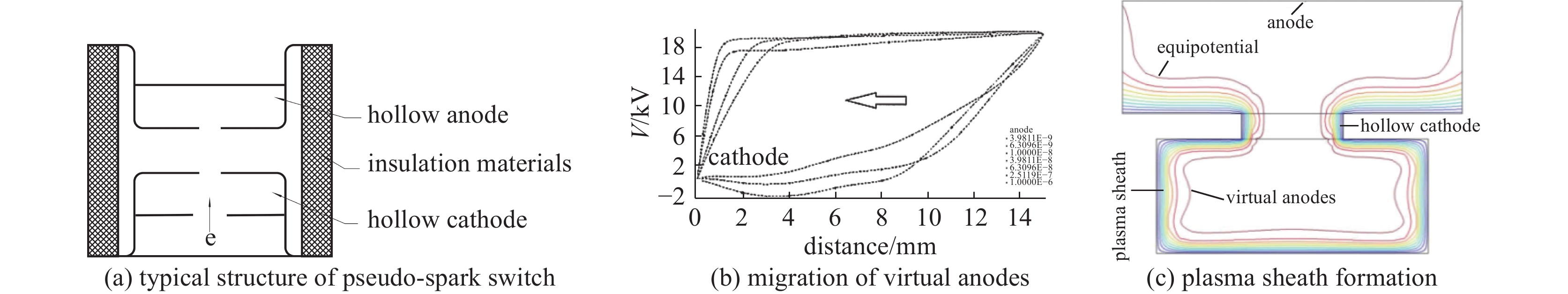
    Fig. 1. Typical structure of pseudo-spark switch & voltage equipotential distribution diagram of pseudo-spark discharge
    Schematic diagram of miniature pseudo-spark switch and equipotential distribution diagram of the cusp and schematic diagram of conventional single-gap pseudo-spark switch
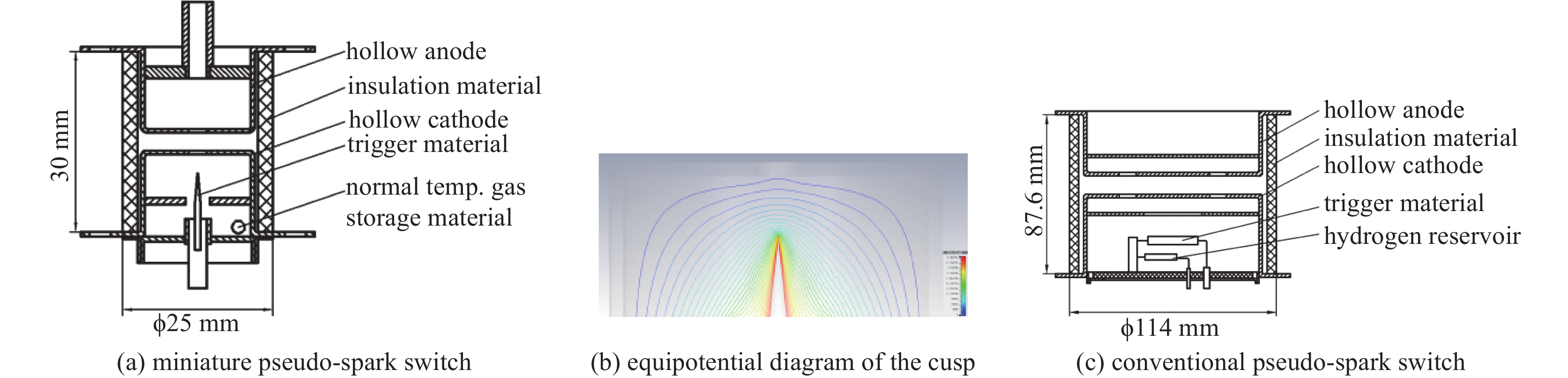
    Fig. 2. Schematic diagram of miniature pseudo-spark switch and equipotential distribution diagram of the cusp and schematic diagram of conventional single-gap pseudo-spark switch
    Comparison between conventional pseudo-spark switch and miniature pseudo-spark switch
    Fig. 3. Comparison between conventional pseudo-spark switch and miniature pseudo-spark switch
    Testing of miniature pseudo-spark switch
    Fig. 4. Testing of miniature pseudo-spark switch
    Test circuit of miniature pseudo-spark switch
    Fig. 5. Test circuit of miniature pseudo-spark switch
    Discharge waveform plot of miniature pseudo-spark switch
    Fig. 6. Discharge waveform plot of miniature pseudo-spark switch
    Diagram of the relationship between forward anode voltage and peak anode pulse current
    Fig. 7. Diagram of the relationship between forward anode voltage and peak anode pulse current
    The distribution plot of anode current delay time
    Fig. 8. The distribution plot of anode current delay time
    peak forward anode voltage (max)/kVpeak anode current/kAhydrogen reservoirsize
    miniature pseudo-spark switch2540noϕ25 mm×30 mm
    conventional pseudo-spark switch4080yesϕ114 mm×87.6 mm
    Table 1. Comparison between miniature pseudo-spark switch and conventional pseudo-spark switch
    peak forward anode voltage/kVpeak anode current/kAdelay time/ns
    28.4245
    313.3250
    417.9268
    522.8247
    627.6245
    731.8266
    836.0275
    939.9252
    Table 2. Experimental data of miniature pseudo-spark switch
    itemsconditions and requirementsresults
    high temperature storagenon-working state; T=55 ℃; t=48 h; recovery time: ≥2 h. Ua=9 kV, Ia=40 kA; once/30 s, 10 times, no breakdown, no corona
    low temperature storagenon-working state; T=−40 ℃; t=24 h; recovery time: ≥2 h. Ua=9 kV, Ia=40 kA; once/30 s, 10 times, no breakdown, no corona
    temperature cyclenon-working state; T1=−40 ℃, t1=2 h; T2=55 ℃, t2=2 h; shift time≤5 min; N=3; recovery time :12 h. Ua=9 kV, Ia=40 kA; once/30 s, 10 times, no breakdown, no corona
    sweep frequency vibrationUa=14 kV, PSD: 0.15 g2/Hz, t=10 min, once for axial and radial. no breakdown, no corona
    Table 3. Reliability test of miniature pseudo-spark switch
    peak forward anode voltage/ self-breakdown voltage/kV minimum operate voltage/kV peak anode current/kA minimum trigger voltage/kV delay time/ns
    miniature pseudo-spark switch100.5400.2280
    RQ-10 trigger tube116324.5
    ZQM-9901 thyratron100.50.20.18350
    hot cathodelife/timessize (mm×mm)total height/mmdraw ability of reverse current
    miniature pseudo-spark switchno>20000ϕ25 mm ×30 mm53yes
    RQ-10 trigger tubeno1000ϕ36.2 mm ×32.5 mm36yes
    ZQM-9901 thyratronyesϕ25 mm ×53 mm79no
    Table 4. Comparison between miniature pseudo-spark switch, trigger tube and miniature thyratron
    Zheng Zhao, Liang Zhou, Xiaoyan Luan, Ming Zhang, Hongfei Yang. Development of miniature pseudo-spark switch[J]. High Power Laser and Particle Beams, 2023, 35(3): 035002
    Download Citation