• Chinese Optics Letters
  • Vol. 20, Issue 7, 073601 (2022)
Jiahao Li1, Mengwei Cao1、2, Weili Liang1, Yilin Zhang1, Zhenwei Xie1、*, and Xiaocong Yuan1
Author Affiliations
  • 1Nanophotonics Research Center, Shenzhen Key Laboratory of Micro-Scale Optical Information Technology & Institute of Microscale Optoelectronics, Shenzhen University, Shenzhen 518060, China
  • 2Department of Physics, Harbin Institute of Technology, Harbin 150001, China
  • show less
    DOI: 10.3788/COL202220.073601 Cite this Article Set citation alerts
    Jiahao Li, Mengwei Cao, Weili Liang, Yilin Zhang, Zhenwei Xie, Xiaocong Yuan. Inverse design of 1D color splitter for high-efficiency color imaging[J]. Chinese Optics Letters, 2022, 20(7): 073601 Copy Citation Text show less
    Compact 1D-CS designed by the inverse design. (a) Schematic diagram of 1D-CS. The spectral range of incident light is 380–780 nm, and the diffraction distance is 2 µm behind the device. There are three target imaging areas (pixels) R, G, and B distributed in the 1D direction. (b) Schematic illustrating the design of a double-layer splitter created from a single-layer one. Structures S1, S2, S3, and S4 represent the initial structure of the single-layer splitter, the final structure of the single-layer splitter, the initial structure of the double-layer splitter, and the final structure of the double-layer splitter, respectively. All devices’ structures in the figure above are cross sections.
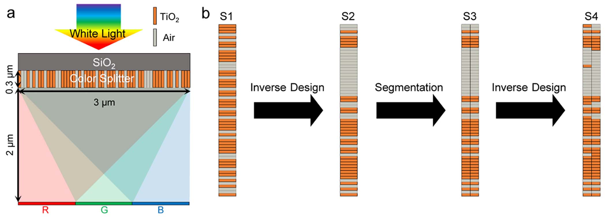
    Fig. 1. Compact 1D-CS designed by the inverse design. (a) Schematic diagram of 1D-CS. The spectral range of incident light is 380–780 nm, and the diffraction distance is 2 µm behind the device. There are three target imaging areas (pixels) R, G, and B distributed in the 1D direction. (b) Schematic illustrating the design of a double-layer splitter created from a single-layer one. Structures S1, S2, S3, and S4 represent the initial structure of the single-layer splitter, the final structure of the single-layer splitter, the initial structure of the double-layer splitter, and the final structure of the double-layer splitter, respectively. All devices’ structures in the figure above are cross sections.
    Simulated splitting characteristics of the designed splitter, calculated from FDTD Solutions. (a) Visible light focusing efficiency of the single-layer splitter at different target color regions (pixel). (b) Visible light focusing efficiency of the double-layer splitter at different target color regions. (c), (d), (e) Field plots at the transmission plane of the single-layer device operating under (c) R (580–780 nm), (d) G (480–580 nm), and (e) B (380–480 nm) light. (f), (g), (h) Field plots at the transmission plane of the double-layer device operating under (f) R (580–780 nm), (g) G (480–580 nm), and (h) B (380–480 nm) light.
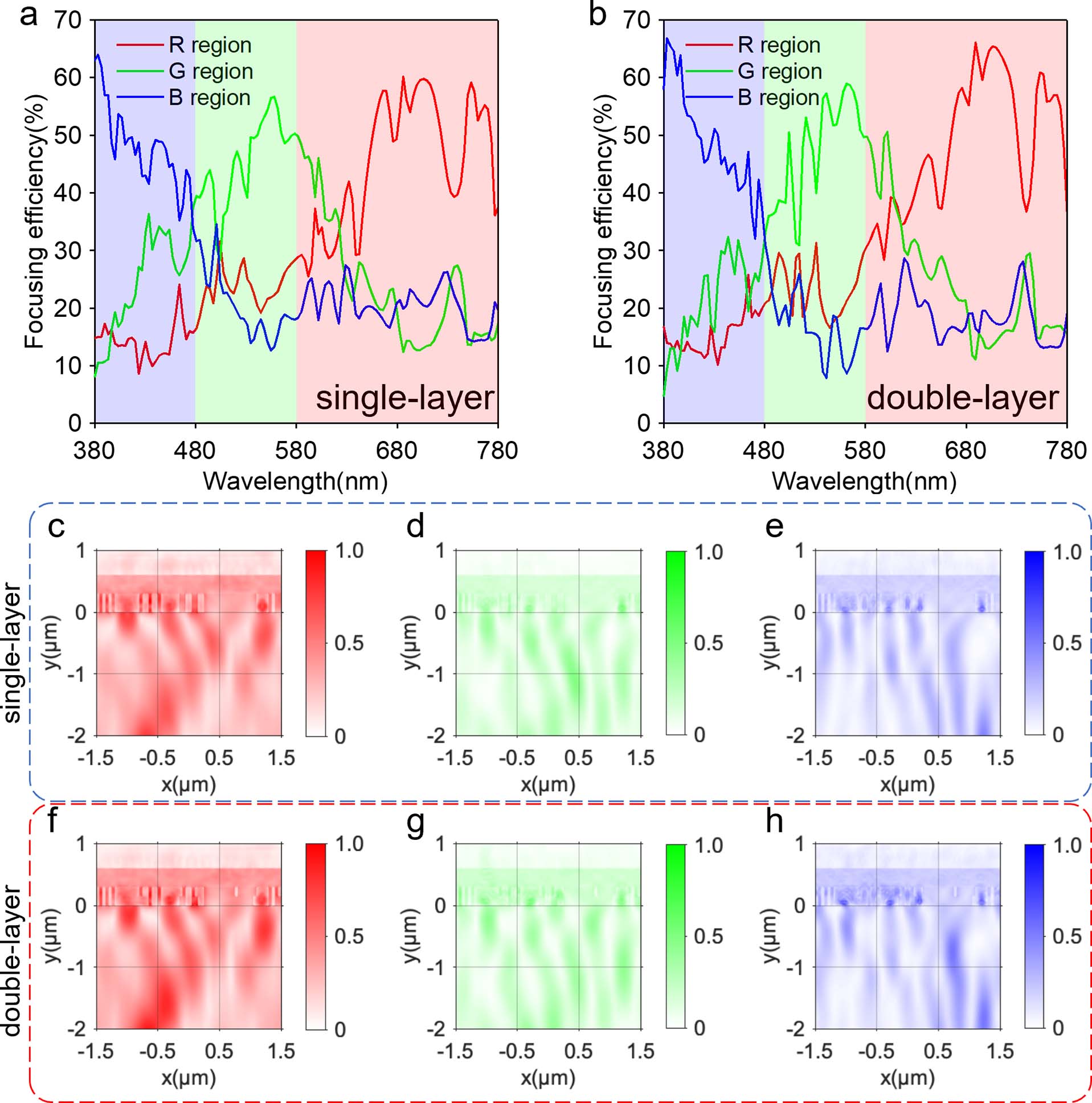
    Fig. 2. Simulated splitting characteristics of the designed splitter, calculated from FDTD Solutions. (a) Visible light focusing efficiency of the single-layer splitter at different target color regions (pixel). (b) Visible light focusing efficiency of the double-layer splitter at different target color regions. (c), (d), (e) Field plots at the transmission plane of the single-layer device operating under (c) R (580–780 nm), (d) G (480–580 nm), and (e) B (380–480 nm) light. (f), (g), (h) Field plots at the transmission plane of the double-layer device operating under (f) R (580–780 nm), (g) G (480–580 nm), and (h) B (380–480 nm) light.
    Simulated sensitivity characteristics of the designed double-layer splitter, calculated from FDTD Solutions. (a) Incident angle sensitivity along the splitting direction (x). Yellow curve corresponds to the average efficiency of three bands (RGB). The R, G, and B curves correspond to the average efficiency of R (580–780 nm), G (480–580 nm), and B (380–480 nm) light, respectively. (b) Polarization angle sensitivity. Yellow curve corresponds to the average efficiency of the three bands (RGB). R, G, and B curves correspond to the average efficiency of R (580–780 nm), G (480–580 nm), and B (380–480 nm) light, respectively. (c)–(h) Field plots at the transmission plane under incident angles of (c)–(e) −4.7° and (f)–(g) 3.3° along the splitting direction (x), operating under (c), (f) R (580–780 nm), (d), (g) G (480–580 nm), and (e), (h) B (380–480 nm) light. (i)–(n) Field plots at the transmission plane under polarization angles of (i)–(k) 45° and (l)–(n) 90°, operating under (i), (l) R (580–780 nm), (j), (m) G (480–580 nm), and (k), (n) B (380–480 nm) light.
    Fig. 3. Simulated sensitivity characteristics of the designed double-layer splitter, calculated from FDTD Solutions. (a) Incident angle sensitivity along the splitting direction (x). Yellow curve corresponds to the average efficiency of three bands (RGB). The R, G, and B curves correspond to the average efficiency of R (580–780 nm), G (480–580 nm), and B (380–480 nm) light, respectively. (b) Polarization angle sensitivity. Yellow curve corresponds to the average efficiency of the three bands (RGB). R, G, and B curves correspond to the average efficiency of R (580–780 nm), G (480–580 nm), and B (380–480 nm) light, respectively. (c)–(h) Field plots at the transmission plane under incident angles of (c)–(e) −4.7° and (f)–(g) 3.3° along the splitting direction (x), operating under (c), (f) R (580–780 nm), (d), (g) G (480–580 nm), and (e), (h) B (380–480 nm) light. (i)–(n) Field plots at the transmission plane under polarization angles of (i)–(k) 45° and (l)–(n) 90°, operating under (i), (l) R (580–780 nm), (j), (m) G (480–580 nm), and (k), (n) B (380–480 nm) light.
    Simulated assembly tolerance of the designed double-layer splitter, calculated from FDTD Solutions. (a) Lateral tolerance. Device moves along the color splitting direction (x). (b) Longitudinal tolerance. Device moves along the diffraction direction (y). Yellow curve corresponds to the average efficiency of the three bands (RGB). The R, G, and B curves correspond to the average efficiency of R (580–780 nm), G (480–580 nm), and B (380–480 nm) light, respectively.
    Fig. 4. Simulated assembly tolerance of the designed double-layer splitter, calculated from FDTD Solutions. (a) Lateral tolerance. Device moves along the color splitting direction (x). (b) Longitudinal tolerance. Device moves along the diffraction direction (y). Yellow curve corresponds to the average efficiency of the three bands (RGB). The R, G, and B curves correspond to the average efficiency of R (580–780 nm), G (480–580 nm), and B (380–480 nm) light, respectively.
    Jiahao Li, Mengwei Cao, Weili Liang, Yilin Zhang, Zhenwei Xie, Xiaocong Yuan. Inverse design of 1D color splitter for high-efficiency color imaging[J]. Chinese Optics Letters, 2022, 20(7): 073601
    Download Citation