Xingxing Huang, Siyuan Chen, Zhixin Wang, Yiguang Wang, Nan Chi. 1.2 Gbit/s visible light transmission based on orthogonal frequency-division multiplexing using a phosphorescent white light-emitting diode and a pre-equalization circuit[J]. Chinese Optics Letters, 2015, 13(10): 100602
Copy Citation Text
We propose a two-cascaded, constant-resistance, symmetrical bridged-T amplitude equalizer for a high-speed visible light communication (VLC) system. With the pre-equalization circuit, the bandwidth of the VLC system can be extended from 12 to 235 MHz using a commercially available phosphorescent white light-emitting diode (LED), a blue filter, and a low-cost PIN photodiode. The data rate is 1.20 Gbit/s, exploiting 16-quadrature amplitude modulation-orthogonal frequency-division multiplexing with a 300 MHz modulation bandwidth over 50 cm of free-space transmission under the pre-forward error correction limit of . To our knowledge, this is the highest bandwidth and the highest data rate ever achieved by using a pre-equalization circuit and white LED in a VLC system.
White light-emitting diodes (LEDs) are considered to be the most promising device for next-generation illumination. LEDs have many advantages, including high efficiency, long life, low cost, low power consumption, and security. Using LEDs for high-speed communication as well as general illumination through visible light communication (VLC) has been an area of growing interest.
The main challenge for achieving high-speed, visible light transmission is the very limited bandwidth (from about 3[1] to 20 MHz[2]) of commercial LEDs. Compared with the triple-chip red–green–blue type LEDs, the phosphor-based white LEDs are more attractive for general illumination due to their lower complexity and lower cost. Although white LEDs have a lower modulation bandwidth because of the limitation caused by the phosphor, many approaches have been reported to extend the modulation bandwidth, such as light filtering, pre-equalization, and post-equalization. Pre-equalization can be used to increase the relative power of the high-frequency component and attenuate the low frequency. In 2008, an 80 Mbit/s on–off keying-non-return-to-zero (OOK-NRZ) data rate using multiple-resonant equalization was realized with a white LED that had a bandwidth of 45 MHz[3]. In 2014, a 662 Mbit/s OOK-NRZ signal was transmitted based on a blue LED by adopting a simple resistors and capacitors pre-equalization circuit[4]. The bandwidth with only a pre-equalized circuit is 112 MHz. These schemes are designed for only OOK modulation with a typical bandwidth that is less than 200 MHz. To further increase the system’s capacity, analog-modulated signals such as high-order quadrature amplitude modulation (QAM) or orthogonal frequency-division multiplexing (OFDM)[5–8] should be considered. These kinds of signals are required for the linear response of the VLC channel. Therefore, obtaining a pre-equalizer with both a large bandwidth and high linearity is a big challenge.
In this Letter, we demonstrate a two-cascaded, constant-resistance, symmetrical bridged-T amplitude equalizer circuit for a high-speed VLC system. Utilizing the cascaded pre-equalization circuit, the bandwidth of the VLC system can be extended from 12 to 235 MHz (starting frequency at 10 MHz) with a commercially available phosphorescent white LED, a blue filter, and a low-cost PIN photodiode. Based on the system above, we successfully demonstrate 16-QAM-OFDM over 50 cm and quadrature phase-shift keying (QPSK) OFDM over 2 m of free-space transmission at 1.2 Gbit/s with a 300 MHz modulation bandwidth and at 0.4 Gbit/s with a 200 MHz modulation bandwidth under the pre-forward error correction (pre-FEC) limit of . Compared with the system that did not use the equalizer, the bit error rate (BER) performance can be improved by 1 order of magnitude. To our knowledge, it is the highest bandwidth and the highest data rate ever achieved by using a pre-equalization circuit and white LED in the VLC systems reported.
Sign up for Chinese Optics Letters TOC. Get the latest issue of Chinese Optics Letters delivered right to you!Sign up now
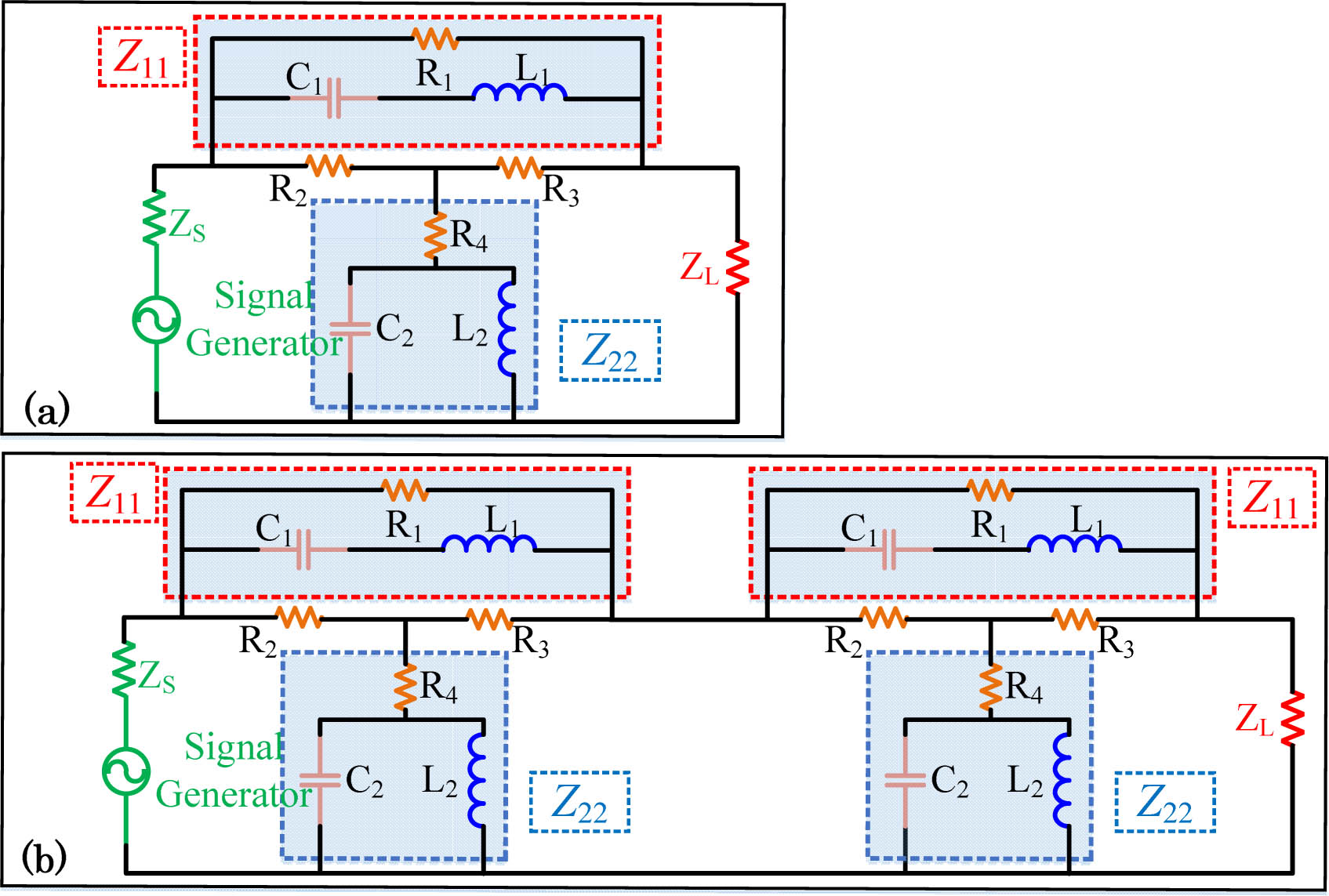
Figure 1(b) shows our proposed two-cascaded, constant-resistance, symmetrical bridged-T amplitude equalizer that was used in the VLC system. For the single equalizer shown in Fig. 1(a), is the equivalent impedance for the network of , , and , and is the equivalent impedance for the network of , , and , while is equal to and both are equal to , and is the load of the circuit.
For constant resistance, the product of must be a constant chosen to be , where is equal to the desired iterative impedance of the network[9] and that is 50 Ω for the equalizer between the arbitrary waveform generator (AWG, 50 Ω output impedance) and the electrical amplifier (EA, 50 Ω input impedance) used in the VLC system.
, can be respectively expressed as where is the angular frequency. To satisfy the condition for arbitrary and consider separate real and imaginary parts, we can use
For easy analysis and realization, we set , . When , the forward transmission gain through the network of a single equalizer can be expressed as where is the output impedance of the signal generator, is the impedance of the load, is the output voltage of the signal generator, is the voltage of the load, and is the frequency response of the single equalizer. Then, is
From Eq. (5), when tends to zero, the maximum limitation of is 1. The equalized bandwidth is set by ; when is relatively small and is constant, the lower frequency response is decided by .
For the two-cascaded equalizer consisting of two of the same single equalizers shown in Fig. 1(b), the forward transmission gain through the network is Regarding the bridged-T equalizer, the main difficulty is to find the precise value so that the equalizer can be well fitted to the individual VLC system. Attention should be focused on both impedance matching and channel flattening. The VLC channel is a kind of complicated exponential decay channel that presents strong nonlinearity. Just one stage of the pre-equalizer could hardly compensate the channel accurately, while the cascaded pre-equalizer can optimize the channel better.
The transmitted signal is carried by a commercially available, phosphorescent white light LED (OSRAM, LCW CRDP.EC). A commercial PIN photodiode (HAMAMATSU S10784, 0.45 A/W sensitivity with bandwidth of 300 MHz at 660 nm), combined with a blue filter in front of it to filter out the slow-responding phosphor component, is used for detecting the light signal. The lens (55 mm diameter) is used to capture a high proportion of light in order to improve the signal-to-noise ratio (SNR) of the system. The VLC system is a line-of-sight (LOS) system.
For a practical equalizer design, the chosen parameters for resistors, capacitors, and inductors should be based on the materials that exist, not the ideal condition deduced in Eq. (3). The parameters used for the proposed bridged-T amplitude equalizer are , , , , .
We measure the S-parameters using a vector network analyzer (VNA, Agilent, N5230C) operating from 10 to 40 GHz. Figure 2 shows the measured forward transmission gain of the proposed two-cascaded, constant-resistance, symmetrical bridged-T amplitude equalizer circuit. The equalizer operates from the lowest frequency, 10 MHz, to the highest, 353 MHz, with about a 38.1 dB dynamic equalized magnitude. The power of the low-frequency components can be attenuated by pre-equalization circuits, while high-frequency part enhanced relatively compared to the lower frequency. In Fig. 2, the VLC system without the blue filter and pre-equalizer shows that the frequency response of the white light is 12 MHz from 10 to 22 MHz, which is limited by the slow response of the phosphor component. With the blue filter filtering out the slow-responding phosphorescent part and the remaining faster frequency response of the blue light, the bandwidth of the system can be extended to 25 MHz. The blue filter can filter out the fluorescent light, including the LOS light from the transmitter LED and the background light. Thus, by using a blue filter, one can improve the system’s performance.
Figure 2.Measured forward transmission gain in different cases.
Because a 300 MHz PIN is used for the detection, the equalizer should achieve a balance between the flattened bandwidth and the receiver responsivity range. The proposed cascaded equalizer can do sophisticated channel compensation; thus, the bandwidth can be further improved to around 235 MHz. The spectrum ripple can be reduced to within 3 dB. The bridged-T equalizer is an analog equalizer, which can support analog signal transmission, such as OFDM. The size of the equalizer is compact, and installation is easy: one simply needs to use passive components, including resistors, capacitors, and inductors.
For the M-QAM-OFDM data transmission experiment shown in Fig. 3, the drive signal is from the AWG (Tektronix AWG710) instead of Port 1 of the VNA. The M-QAM-OFDM waveform is loaded into the AWG, whose output serves as the input of the VLC system. At the receiver, the optical signal is detected by the PIN detector and recorded by a real-time digital oscilloscope (OSC, Agilent 54855A). A control computer is used to acquire a waveform from the OSC for subsequent further offline procession to recover the original signal. Then, the received signals are down-converted to baseband and processed with the inverse procedure of an M-QAM-OFDM encoder. At last, we test the BER performance of the M-QAM-OFDM. The VLC system is an incoherent transmission system that uses intensity modulation and direct detection. The OFDM used is a direct-detection optical OFDM and should be the real valued data. Up-conversion to an intermediate frequency is used to generate the real valued signal. The parameters of generated the M-QAM-OFDM signals include: subcarrier , , and training . The VLC channel is a slowly varying channel; therefore, a 5% training sequence is long enough for the channel estimation.
In the VLC system data transmission demonstration, we first measured the BER results based on 16-QAM-OFDM with a 300 MHz modulation bandwidth from 9.375 to 309.375 MHz versus the signal driving voltage of the AWG and the bias current of a white LED with and without a pre-equalizer at the distance of 50 cm. The signal driving peak-to-peak voltage (Vpp) of the AWG varies from 0.1 to 1.6 Vpp, and the bias current is from 89 to 251 mA. The measured BER results versus the signal driving voltage and bias current with and without the pre-equalizer are shown in Figs. 4 and 5. Clearly, the VLC system with the pre-equalizer can outperform the system without the pre-equalizer. The optimum operation range for the bias current is between 170 and 260 mA; for the driving voltage, it is around 1.1–1.4 Vpp. We get the optimal point driving voltage of 1.2 and 0.2 Vpp for the systems with and without the pre-equalizer, respectively, and the optimal bias currents are both 211 mA. The corresponding BER results are and , respectively. The performance of the VLC system can be greatly improved by using the equalizer, and the BER performance for the 16-QAM-OFDM can be reduced by an order of magnitude. The illuminance of the background light is about 70.1 lux. The illuminance from the transmitter LED is about 1740.2 lux under the bias current of 211 mA and distance of 50 cm. The background scattering light acts as the noise of the receiver and has very little influence on the receiver.
Figure 4.Measured BER results versus the signal driving voltage and the bias current with the pre-equalizer.
Because of the nonlinearity of the LED, an optimal range of the bias current of the LED should be investigated to achieve a quasi-linear operation. Both a smaller and bigger bias current will make the signal distorted. The driving voltage and bias current should be carefully selected to minimize the signal clipping and magnitude distortion[10].
At the optimal driving voltage of 1.2 Vpp and bias current of 211 mA, we measure the BER results at different bandwidths of 200, 250, 300, and 350 MHz, and at different distances of 50, 100, 150, and 200 cm using the pre-equalizer. For the modulation bandwidths of 200, 250, 300, and 350 MHz, the data rates will be 0.8, 1.0, 1.2, and 1.4 Gbit/s using the 16-QAM-OFDM, or 0.4, 0.5, 0.6, and 0.7 Gbit/s using the QPSK-OFDM. From Figs. 6 and 7, it can be seen that the BER results degrade with the increase of the data rate and transmission distance because of the decreasing SNR performance. The total data rates are 1.2, 1.2, 0.7, and 0.4 Gbit/s at the distance of 50, 100, 150, and 200 cm, respectively, with the BER under the pre-FEC limit of . The average SNR is 17.8 dB when the bandwidth is 300 MHz at the distance of 50 cm, so the maximum QAM order is 16[11]. For the case of the 200 cm transmission distance and 200 MHz bandwidth, the measured SNR is 10.2 dB, which leads to the maximum 4-QAM modulation.
Figure 6.BERs at different data rates and distances of the 16-QAM-OFDM.
In conclusion, we propose a two-cascaded, constant-resistance, symmetrical bridged-T amplitude equalizer used for a high-speed VLC system. Using the proposed pre-equalization circuit and a blue filter, the bandwidth of the VLC system can be increased from 12 to 235 MHz (starting frequency at 10 MHz) with a commercial phosphorescent white light LED and a low-cost PIN photodiode. The overall data rate is 1.20 Gbit/s with 300 MHz modulation bandwidth using the equalizer by employing 16-QAM-OFDM based on a single, commercially available phosphorescent white LED and a low-cost PIN with a BER under the pre-FEC limit of after 50 cm of free-space transmission. With a longer distance of about 200 cm, a 0.4 Gbit/s data rate can be achieved using the QPSK-OFDM signal of the 200 MHz modulation bandwidth. The BER performance can be improved at least by 1 order of magnitude using 16-QAM-OFDM transmission compared with the system that does not use the equalizer. To the best of our knowledge, this is the highest bandwidth and the highest data rate ever achieved by using a pre-equalization circuit and a white light LED in the VLC systems reported. To obtain an even wider bandwidth VLC system, the bandwidth of the PIN detector, a specially designed LED structure, and the transmission distance should be considered as limiting factors. A VLC system over 1 GHz should be investigated in the future.
Xingxing Huang, Siyuan Chen, Zhixin Wang, Yiguang Wang, Nan Chi. 1.2 Gbit/s visible light transmission based on orthogonal frequency-division multiplexing using a phosphorescent white light-emitting diode and a pre-equalization circuit[J]. Chinese Optics Letters, 2015, 13(10): 100602