• High Power Laser Science and Engineering
  • Vol. 11, Issue 5, 05000e56 (2023)
Scott Feister1, Kevin Cassou2, Stephen Dann3, Andreas Döpp4, Philippe Gauron2, Anthony J. Gonsalves5, Archis Joglekar6、7, Victoria Marshall3, Olivier Neveu2, Hans-Peter Schlenvoigt8, Matthew J. V. Streeter9, and Charlotte A. J. Palmer9、*
Author Affiliations
  • 1California State University Channel Islands, Camarillo, California, USA
  • 2Université Paris-Saclay, CNRS/IN2P3, IJCLab, Orsay, France
  • 3Central Laser Facility, STFC Rutherford Appleton Laboratory, Didcot, UK
  • 4Ludwig–Maximilians–Universität München, Garching, Germany
  • 5BELLA Center, Lawrence Berkeley National Laboratory, Berkeley, California, USA
  • 6Department of Nuclear Engineering and Radiological Sciences, University of Michigan, Ann Arbor, Michigan, USA
  • 7Ergodic LLC, San Francisco, California, USA
  • 8Helmholtz-Zentrum Dresden – Rossendorf, Dresden, Germany
  • 9Queen’s University Belfast, Belfast, UK
  • show less
    DOI: 10.1017/hpl.2023.49 Cite this Article Set citation alerts
    Scott Feister, Kevin Cassou, Stephen Dann, Andreas Döpp, Philippe Gauron, Anthony J. Gonsalves, Archis Joglekar, Victoria Marshall, Olivier Neveu, Hans-Peter Schlenvoigt, Matthew J. V. Streeter, Charlotte A. J. Palmer. Control systems and data management for high-power laser facilities[J]. High Power Laser Science and Engineering, 2023, 11(5): 05000e56 Copy Citation Text show less
    (a) Diagram of a high-power laser facility without a laboratory-wide control system. People tie the subsystems together. For example, a person might adjust parameters on the laser amplifier subsystem in response to observations from the target-chamber subsystem. (b) Diagram of a facility with a laboratory-wide control system. Consistent implementation throughout the facility opens new communication pathways between subsystems. These new pathways enable laboratory-wide automation and control feedback loops without human mediation. Humans retain communication with all subsystems.
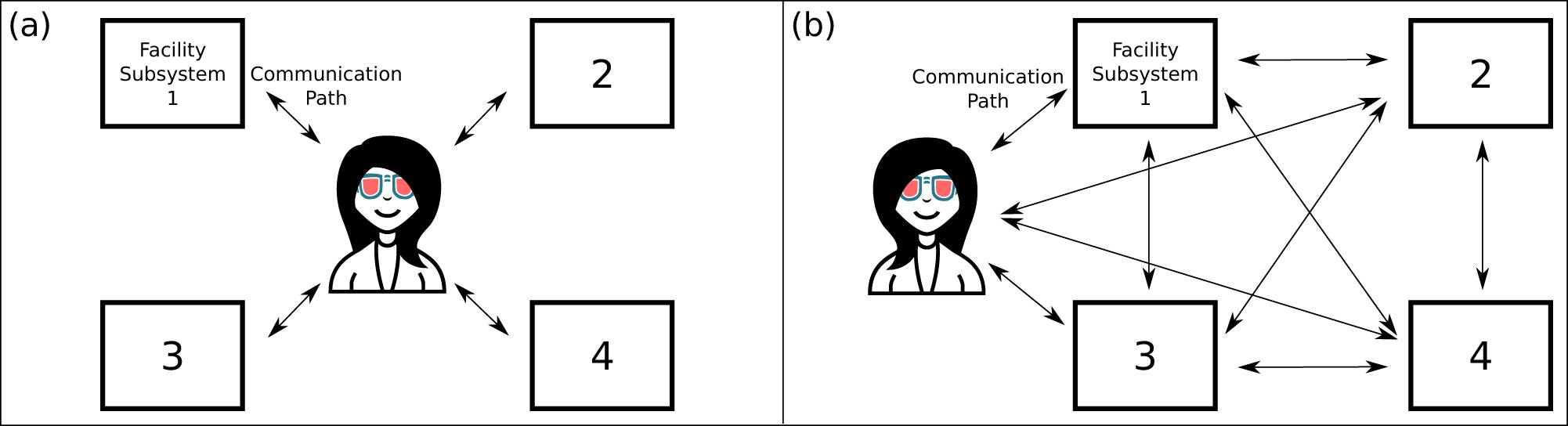
    Fig. 1. (a) Diagram of a high-power laser facility without a laboratory-wide control system. People tie the subsystems together. For example, a person might adjust parameters on the laser amplifier subsystem in response to observations from the target-chamber subsystem. (b) Diagram of a facility with a laboratory-wide control system. Consistent implementation throughout the facility opens new communication pathways between subsystems. These new pathways enable laboratory-wide automation and control feedback loops without human mediation. Humans retain communication with all subsystems.
    Engineers and scientists (represented with maroon and blue icons, respectively) manually conduct steps in the operational sequences for Draco at HZDR. (a) Facility laser shot sequence diagram for ion acceleration experiments. Note the many steps in which people tie together subsystems. The central blue circle indicates the laser shot sequence, executed and surveilled by scientists. Automated storage is part of many subsystems. (b) Manual logging to complement and complete the data storage, to curate and enrich with the metadata.
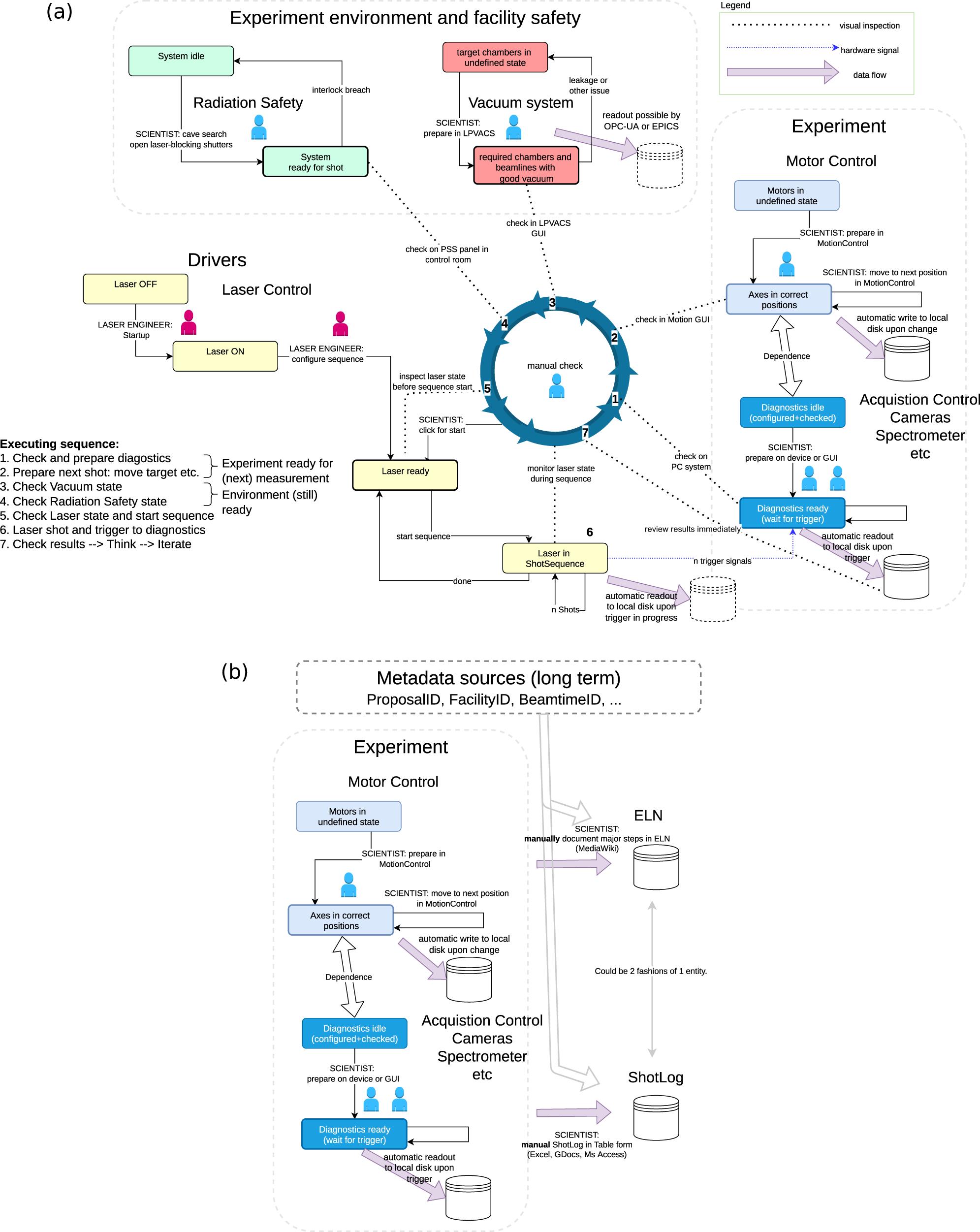
    Fig. 2. Engineers and scientists (represented with maroon and blue icons, respectively) manually conduct steps in the operational sequences for Draco at HZDR. (a) Facility laser shot sequence diagram for ion acceleration experiments. Note the many steps in which people tie together subsystems. The central blue circle indicates the laser shot sequence, executed and surveilled by scientists. Automated storage is part of many subsystems. (b) Manual logging to complement and complete the data storage, to curate and enrich with the metadata.
    Hardware and software overview of the GEECS control system, highlighting the layered modular approach. The hardware view is shown on the left, with multiple devices attached to a given computer, the number of which is determined by the system resources. The software running on the computers is shown on the right, which sends data and receives commands through the network infrastructure. The GUIs and the database receive data continuously, with the latter limited to scalar data. The file server receives scan data (which includes scalar, vector and image data) when the user initiates a ‘scan’, which can be linear, from a script, or via the GEECS Python API. All devices are controlled by an instance of the same executable, which calls device-specific code in a plugin architecture. GUIs are custom executables, but share the same communication code to receive data and send commands.
    Fig. 3. Hardware and software overview of the GEECS control system, highlighting the layered modular approach. The hardware view is shown on the left, with multiple devices attached to a given computer, the number of which is determined by the system resources. The software running on the computers is shown on the right, which sends data and receives commands through the network infrastructure. The GUIs and the database receive data continuously, with the latter limited to scalar data. The file server receives scan data (which includes scalar, vector and image data) when the user initiates a ‘scan’, which can be linear, from a script, or via the GEECS Python API. All devices are controlled by an instance of the same executable, which calls device-specific code in a plugin architecture. GUIs are custom executables, but share the same communication code to receive data and send commands.
    Architecture of the Gemini Control System. EPICS input/output controllers (IOCs) are software + hardware layers providing an abstraction between low-level device hardware and high-level control system software. Legacy hardware is connected into the system through a legacy interface, Control Interface #2. A differentiation is made between EPICS-interfacing components and connections (in blue) and bespoke components and connections (in orange). Clients for device data include human control interfaces, informational laboratory displays, automation software and archival data collectors.
    Fig. 4. Architecture of the Gemini Control System. EPICS input/output controllers (IOCs) are software + hardware layers providing an abstraction between low-level device hardware and high-level control system software. Legacy hardware is connected into the system through a legacy interface, Control Interface #2. A differentiation is made between EPICS-interfacing components and connections (in blue) and bespoke components and connections (in orange). Clients for device data include human control interfaces, informational laboratory displays, automation software and archival data collectors.
    Illustration of the relation between the client and device server and the Tango database running on the TANGO_HOST. This simple system constitutes the minimal Tango configuration.
    Fig. 5. Illustration of the relation between the client and device server and the Tango database running on the TANGO_HOST. This simple system constitutes the minimal Tango configuration.
    Illustration of the standard Tango device structure between the Tango Controls software communication bus and the hardware. The interface is common to all the devices for all the device classes and can be generated using the POGO tool[93" target="_self" style="display: inline;">93]. The hardware driver part code has to be written by the developer on the top of an existing driver, software development kit or communication protocol.
    Fig. 6. Illustration of the standard Tango device structure between the Tango Controls software communication bus and the hardware. The interface is common to all the devices for all the device classes and can be generated using the POGO tool[93]. The hardware driver part code has to be written by the developer on the top of an existing driver, software development kit or communication protocol.
    Schematic of the PALLAS control command and acquisition system. System elements are represented by coloured rectangles (colour legend in the lower-left corner), with links between elements represented as coloured lines. Green lines show Tango communication pathways, black lines indicate wired Ethernet connections, yellow lines show wired USB-3 connections and grey lines indicate wired RS232 connections. For better readability, some hardware is not shown. The system can be divided into four parts: (1) the main Tango server units (light blue), the heart of the system running the Tango database, archiving system and webservers; (2) the embedded computer units (light grey) running some Tango device servers (sometimes located adjacent to scientific hardware due to limited cable lengths for USB-3 or RS232 device connections); (3) the hardware motor controllers (dark blue), the PLCs (green) and the area detectors (dark yellow); (4) examples of clients, pyTango and Taurus, which need Tango Controls software installed on a client machine, and WebClients, which requires only a web browser and a connection to the local network. Below the coloured rectangle for each server unit or embedded computer unit, device servers running on that unit are indicated in italic font within white-filled rectangles. These are named LimaCCD, eoGENTENC, mrcLSB… and represent device servers openly developed and available for download[101" target="_self" style="display: inline;">101,102" target="_self" style="display: inline;">102]. The laser system has three connection points into the PALLAS local network: the laserix-arch where laser data are stored, the shotCounter that uniquely identifies laser shots and the TangoGateway running a device server that gives Tango access to certain laser controls. The laser system has its own separated network. As shown in the upper-right corner, some of the webservers can be accessed from either side of the PALLAS local network through a gateway, and data storage is done outside the local network for easier and broader data sharing.
    Fig. 7. Schematic of the PALLAS control command and acquisition system. System elements are represented by coloured rectangles (colour legend in the lower-left corner), with links between elements represented as coloured lines. Green lines show Tango communication pathways, black lines indicate wired Ethernet connections, yellow lines show wired USB-3 connections and grey lines indicate wired RS232 connections. For better readability, some hardware is not shown. The system can be divided into four parts: (1) the main Tango server units (light blue), the heart of the system running the Tango database, archiving system and webservers; (2) the embedded computer units (light grey) running some Tango device servers (sometimes located adjacent to scientific hardware due to limited cable lengths for USB-3 or RS232 device connections); (3) the hardware motor controllers (dark blue), the PLCs (green) and the area detectors (dark yellow); (4) examples of clients, pyTango and Taurus, which need Tango Controls software installed on a client machine, and WebClients, which requires only a web browser and a connection to the local network. Below the coloured rectangle for each server unit or embedded computer unit, device servers running on that unit are indicated in italic font within white-filled rectangles. These are named LimaCCD, eoGENTENC, mrcLSB… and represent device servers openly developed and available for download[101,102]. The laser system has three connection points into the PALLAS local network: the laserix-arch where laser data are stored, the shotCounter that uniquely identifies laser shots and the TangoGateway running a device server that gives Tango access to certain laser controls. The laser system has its own separated network. As shown in the upper-right corner, some of the webservers can be accessed from either side of the PALLAS local network through a gateway, and data storage is done outside the local network for easier and broader data sharing.
    Timing and event generation system for the time and shot stamping of the data. A transistor-transistor logic (TTL) signal can be tuned from –10 to 40 ms around each laser pulse at 10 Hz. The ShotCounter generates a unique 64-bit shot identification. The ZMQ message contains the SHOTID and STATUS of the 16 analog inputs of the NI-PCIe 6320 card. Archiving data is set by the SHOTRECORDER device server (DS) and then an archiver (EVENT SUBSCRIBER DS) stores the data to the target database.
    Fig. 8. Timing and event generation system for the time and shot stamping of the data. A transistor-transistor logic (TTL) signal can be tuned from –10 to 40 ms around each laser pulse at 10 Hz. The ShotCounter generates a unique 64-bit shot identification. The ZMQ message contains the SHOTID and STATUS of the 16 analog inputs of the NI-PCIe 6320 card. Archiving data is set by the SHOTRECORDER device server (DS) and then an archiver (EVENT SUBSCRIBER DS) stores the data to the target database.
    Scott Feister, Kevin Cassou, Stephen Dann, Andreas Döpp, Philippe Gauron, Anthony J. Gonsalves, Archis Joglekar, Victoria Marshall, Olivier Neveu, Hans-Peter Schlenvoigt, Matthew J. V. Streeter, Charlotte A. J. Palmer. Control systems and data management for high-power laser facilities[J]. High Power Laser Science and Engineering, 2023, 11(5): 05000e56
    Download Citation