
Yi-Fan Zhu, Tao Geng. Generation of high-quality circular Airy beams in laser resonator [J]. Acta Physica Sinica, 2020, 69(1): 014205-1
- Acta Physica Sinica
- Vol. 69, Issue 1, 014205-1 (2020)
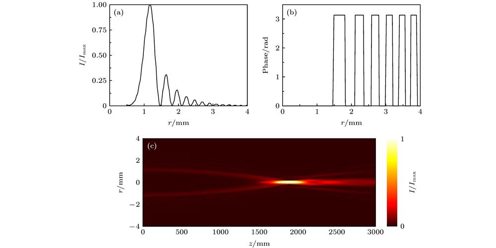
Fig. 1. (a) Intensity distributions of the CAB at the initial plane; (b) phase distributions of the CAB at the initial plane; (c) intensity distributions of the CAB during propagation in the r -z plane.
(a) CAB初始面的光强分布; (b) CAB初始面的相位分布; (c) CAB的侧面光强分布
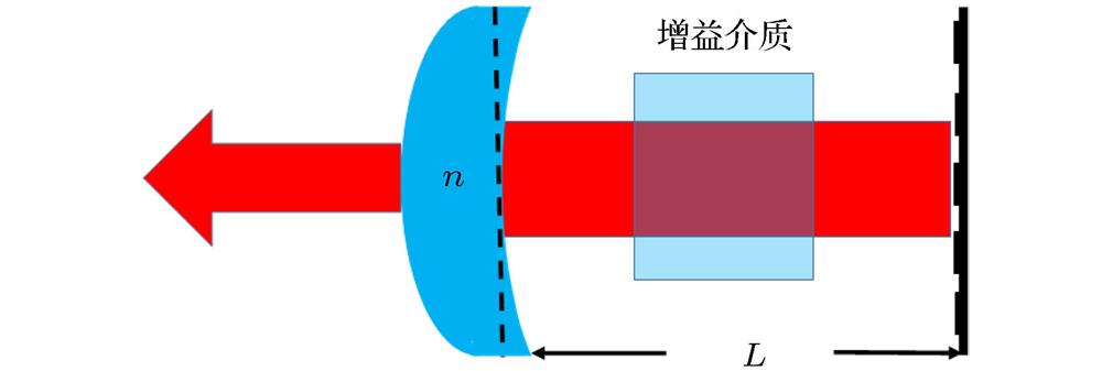
Fig. 2. Schematic of the laser resonator configuration for CAB generation.谐振腔示意图
Fig. 3. Calculation results of the intensity distributions of the modes by using Fox-Li method with different parameters: (a) r 0 = 1 mm, w = 0.2 mm and a = 0.15; (b) r 0 = 1.1 mm, w = 0.22 mm and a = 0.17; (c) r 0 = 1.2 mm, w = 0.25 mm and a = 0.2.
不同参数条件下, 使用Fox-Li方法计算获得的腔内光场模式分布 (a) r 0 = 1 mm, w = 0.2 mm和a = 0.15; (b) r 0 = 1.1 mm, w = 0.22 mm和a = 0.17; (c) r 0 = 1.2 mm, w = 0.25 mm和a = 0.2
Fig. 4. Radial intensity distributions of the ideal CAB and the beams produced by different methods: (a) r 0 = 1 mm, w = 0.2 mm and a = 0.15; (b) r 0 = 1.1 mm, w = 0.22 mm and a = 0.17; (c) r 0 = 1.2 mm, w = 0.25 mm and a = 0.2.
理想CAB和使用不同方法产生的光束的径向光强分布 (a) r 0 = 1 mm, w = 0.2 mm和a = 0.15; (b) r 0 = 1.1 mm, w = 0.22 mm和a = 0.17; (c) r 0 = 1.2 mm, w = 0.25 mm和a = 0.2
Fig. 5. On-axis intensity contrast of the ideal CAB and the beams produced by different methods: (a) r 0 = 1 mm, w = 0.2 mm and a = 0.15; (b) r 0 = 1.1 mm, w = 0.22 mm and a = 0.17; (c) r 0 = 1.2 mm, w = 0.25 mm and a = 0.2.
理想CAB和使用不同方法产生的光束的光轴光强分布 (a) r 0 = 1 mm, w = 0.2 mm和a = 0.15; (b) r 0 = 1.1 mm, w = 0.22 mm和a = 0.17; (c) r 0 = 1.2 mm, w = 0.25 mm和a = 0.2
Fig. 6. The influence of the alignment errors on formation of the fundamental mode with
,
and
: (a)
and S of the fundamental mode as a function of
; (b)
and S of the fundamental mode as a function of
光束参数为
,
和
时, 系统对准误差对产生光束质量的影响 (a)基模的
以及S 与腔长误差
的关系; (b)基模的
以及S与同轴度误差
的关系
Fig. 7. and S of the fundamental mode as a function of
.
基模的
以及S 与
的关系
|
Table 1. The phase distributions of the diffractive optical elements, the three largest
and the calculated intensity distributions of corresponding modes with different parameters.
不同参数条件下的衍射光学元件上的相位分布和计算获得的最大3个
对应模式的光强分布


Set citation alerts for the article
Please enter your email address

© Copyright 2018-2021 | Chinese Laser Press. All Rights Reserved 沪ICP备15018463号-20