1School of Science, Changchun University of Science and Technology, Changchun 130022, China
2State Key Laboratory of Luminescence and Applications, Changchun Institute of Optics, Fine Mechanics and Physics, Chinese Academy of Sciences, Changchun 130033, China
This Letter proposes a method to balance the gain and loss of the orthogonally polarized emissions of dual wavelengths in a solid laser cavity. By adjusting the tilt angle of the uncoated glass plate inserted into the cavity, the gain and loss of the orthogonally polarized emission lines with small intervals can be balanced to equalize the oscillation thresholds of the orthogonally polarized dual wavelengths. We select the birefringent crystal Nd:LiYF (Nd:YLF) as the gain media, and theoretically analyze the simultaneous oscillation conditions of dual wavelengths with - and -polarized emissions from a four-level transition ( and ) in . A simple linear cavity structure is adopted in the experiment, and stable CW orthogonally polarized dual-wavelength laser outputs of 1047, and 1053, 1321, and 1313 nm are obtained.
In the past few years, the dual-wavelength laser is a hot international research topic[1–5]. Since its structure is compact and can be miniaturized, the solid-state dual-wavelength laser is able to supply more output power, and can cover wider bands[6,7]. Over the past decade, there has been considerable interest in developing dual-wavelength lasers, especially Nd-doped dual-wavelength lasers[8–11]. The Nd:LiYF (Nd:YLF) crystal is an important material for use in dual-wavelength lasers with orthogonal polarizations. The -doped laser crystal has three main transition lines: , , and . Currently, there are two main types of solid-state dual-wavelength lasers. The first type is a wide-spaced dual-wavelength laser, the lasing wavelengths of which are mainly from two of the three transition lines of the Nd-doped laser crystal. And the second type is a narrow-spaced dual-wavelength laser. Dual-wavelength operation of this type of laser is realized by the splitting of the Stark levels of a transition line of a Nd-doped laser crystal. Since the wavelength interval is very small (), utilizing the current coating technique for separation is very difficult. Actually, even if the coating parameters can reach the pre-calculated theoretical values, simultaneous dual-wavelength oscillation is difficult to obtain because of the uncertain other parameters of the laser. So far, there are two main approaches to making this kind of dual-wavelength laser. The first approach is to insert some element inside the cavity and use the element’s different characteristics for dual wavelengths to balance their gain-to-loss[12–15]. Moreover, in some Nd-doped laser crystals, the emission cross sections of the two transition wavelengths from some Stark energy level splits are close. Thus, in realizing one transition wavelength operation caused by a Stark split, the other wavelength would also oscillate, provided we did not take any measures[16–20]. Beams of dual wavelengths with small intervals realized by the method above always have the same polarization. The second method uses a polarized beam splitter or a Fabry–Perot etalon with a tilt angle to separate the two wavelength beams with orthogonal polarizations and keep them oscillating in their own cavities. Then the film system of each cavity’s output mirror is designed to balance the gain-to-loss of the dual wavelengths, so that the thresholds of the dual wavelengths can be equalized[21–25]. By a nonlinear difference-frequency[26], this kind of small-interval orthogonally polarized dual-wavelength laser beam can realize coherent terahertz (THz) with a frequency range of 0.1–3 Hz. This has great potential applications in THz imaging, THz remote sensing[27], THz spectroscopy[28,29], laser interferometry[30], and precision metrology[31].
In this Letter, we put forward a new method to generate orthogonally polarized dual-wavelength lasers. We inserted an uncoated glass plate into the cavity, and changed its tilt angle to modulate the loss difference of the dual wavelengths in the cavity to obtain the dual-wavelength gain-to-loss balance. We used the birefringent crystal Nd:YLF as the gain media, and realized stable CW orthogonally polarized dual-wavelength laser outputs of 1047 and 1053 nm, and of 1321 and 1313 nm.
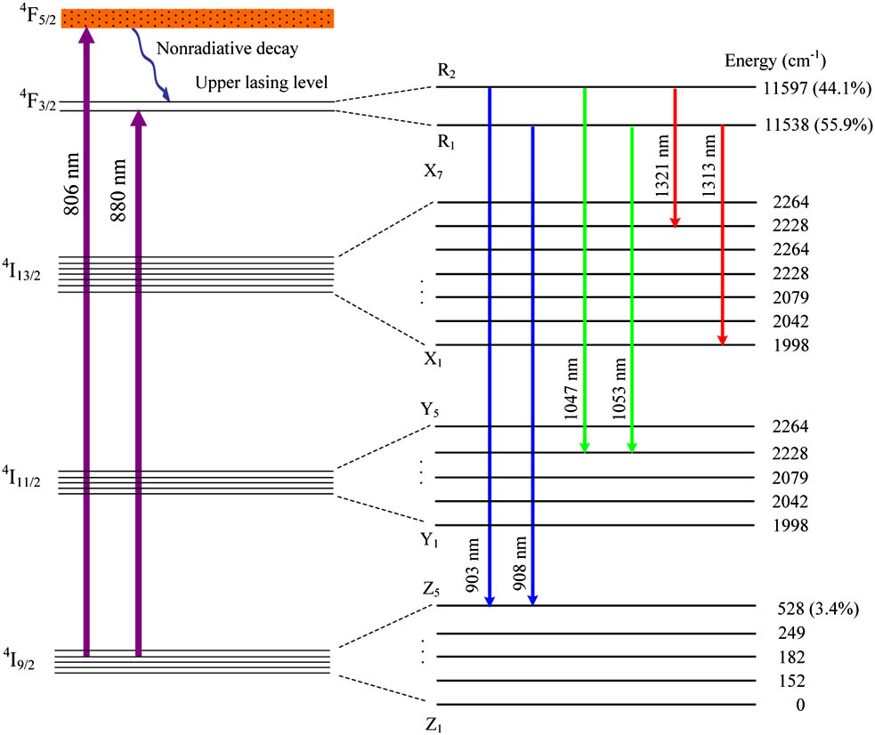
We chose an a-cut Nd:YLF birefringent crystal as the gain media to generate the orthogonally polarized dual-wavelength laser. The energy level scheme of Nd:YLF at room temperature is shown in Fig. 1. An transition can result in a 1047 nm -polarized emission ( axis) and a 1053 nm -polarized emission ( axis), the stimulated emission cross sections of which are and , respectively[32]. An transition can result in 1321 nm -polarized and 1313 nm -polarized emissions, the stimulated emission cross sections of which are and , respectively[33]. An transition can result in 903 nm -polarized and 908 nm -polarized emissions, the stimulated emission cross sections of which are and , respectively[34]. The stimulated emission cross sections of the two orthogonally polarized wavelengths are different, and the ratios of the population in the Stokes sub-energy-level and the total population in the upper energy level of these two orthogonally polarized emissions are also different. Therefore, in order to simultaneously oscillate the dual wavelengths, we should correspondingly adjust the cavity mode size, output loss, and so on, to balance the output of the dual-wavelength laser oscillation so as to equalize the competitive powers of the dual-wavelength oscillations. This way, we would not suppress one wavelength oscillation because of the more competitive oscillation of the other wavelength.
Sign up for Chinese Optics Letters TOC. Get the latest issue of Chinese Optics Letters delivered right to you!Sign up now
Figure 1.Nd:YLF energy level scheme at room temperature.
The four-level Nd:YLF laser corresponds to the and transitions. In the transition, when the gain is at maximum, a 1047 nm -polarization emission is outputted[35,36]. After applying measures to select the frequency, a 1053 nnm -polarized emission can be obtained[37,38]. In the transition, a single wavelength output of either 1321[39,40] or 1313 nm[41,42] around 1.3 μm has been reported. Dual-wavelength outputs of 1047 and 1053 nm, or 1321 and 1313 nm have never been reported. The laser threshold of the four-level system can be expressed as[43]where and 2 represent the wavelengths of - and -polarization directions, respectively. is the round-trip loss in the cavity, is the round-trip transmission loss, and is the passive loss of the transmission with the corresponding transition wavelength. is the absorption coefficient of the Nd:YLF crystal, is the length of the Nd:YLF crystal, and is the cavity length. is the quantum efficiency of the pump beam, is the ratio of the Stoke’s particle number in the upper energy level to the total particle number, and is the stimulated emission cross-section. is the laser’s upper-level lifetime, and and are the normalized cavity mode intensity distribution of the transition wavelength and the pump beam intensity distribution, which are expressed aswhere and are the pump wavelength and the laser wavelength, respectively. is the pump photon energy, and and are the beam waists of the pump light and the laser in the gain media. in Eq. (2) is the distribution of the pump beam, which can be expressed as
in Eq. (4) is the quality factor of pump beam, is the focal plane of the pump beam in the gain media, and is the refractive index of the gain media. From Eqs. (1)–(4), the dual-wavelength threshold ratio is expressed as
The dual-wavelength orthogonally polarized laser can oscillate simultaneously only when the thresholds are equalized. The ratio between the thresholds of the orthogonally polarized wavelengths is . From Eq. (5), it can be seen that if we adopt a simple two-mirror linear cavity, , , , the Stoke’s sub-bands in the upper energy level that generate orthogonally polarized wavelengths will be different. Namely, , and the emission cross-sections are different, namely . When the wavelength spacing is smaller, it is difficult for the coating technique to separate the transmissivities, namely , which leads to .Thus, . Supposing , the weaker spectrum line would oscillate first. Only when the pump power kept increasing could the stronger spectrum line start oscillating. Because the gain competition between the two wavelengths cannot be balanced, the dual-wavelength output cannot be stable. If , the stronger spectral line would oscillate first. The weaker spectral line would be suppressed to higher limits, and only very a high pump power could reach the thresholds. Actually, the ratio between these two kinds of transition branches is always very big. Moreover, there exists a gain competition between the two wavelengths, so in order to make different frequencies oscillate simultaneously in the same crystal, the losses of the lasers with different frequencies must be artificially modulated to approximately equalize the losses of the different frequencies. This weakens the mode competition; thus, the dual wavelengths can output simultaneously. Therefore, the key to generating a dual-wavelength beam is to modulate the mode loss in order that the oscillation conditions of the dual wavelengths are equalized. Since Shen et al. first demonstrated the threshold equilibrium condition of dual-wavelength simultaneous oscillations, many researchers have obtained dual-wavelength simultaneous outputs. Generally, researchers have controlled the round-trip transmission loss of the transmission coupling system. The coating technique is always used to change the round-trip loss of the cavity, which is difficult to meet the requirements for dual-wavelength lasers with small wavelength spacing. So we insert an uncoated glass plate inside the cavity, and change the losses of the orthogonally polarized dual wavelengths in the cavity by adjusting the tilt angle of the glass plate. From the Fresnel equation[44], we can obtain the reflectivities and of the orthogonally polarized -wave and -wave while they pass through the uncoated glass plate. This can also be regarded as single-trip reflection losses and of the orthogonally polarized dual wavelengths. where and are the incident angle and the refractive angle of the laser beam on the glass plate, respectively. and satisfy the refraction law . Figure 2 shows the relation curves of the incident angle versus the single reflection losses and . It can be seen from Fig. 2 that , so can be regarded as the loss in the polarization direction of the stronger spectral line in the dual wavelengths, and can be regarded as the loss in the polarization direction of the weaker spectral line in the dual wavelengths. Thus, a balance between the losses of the two lasers with different frequencies can be obtained. In the experiment, when we were placing the Nd:YLF birefringent crystal, the bigger emission cross-section of the Nd:YLF was placed in the same direction as the -wave polarization. Therefore, after inserting the uncoated glass plate inside the cavity, the round-trip loss in the cavity can be expressed as where , represent the laser wavelengths of the and polarization directions.
Figure 2.The dependence of the relative losses for the and waves on the incident angle for the dual-wavelength operation.
For the transition, the transmittance of the 1047 and 1053 nm output coupling mirrors is , with a passive loss of . For the transition, the transmittance of the 1321 and 1313 nm output coupling mirrors is , with a passive loss of . By substituting Eq. (8) into Eq. (5), we can obtain the dependence of the ratio of the laser thresholds on the incident angle for the operation of the orthogonally polarized dual-wavelength laser, as shown in Fig. 3. From Fig. 3, it can be seen that for the transition, when incident angle , . At this moment, a gain-to-loss balance of 1047 and 1053 nm in the orthogonally polarized dual-wavelength operation is reached, and the dual-wavelength mode competence effect is at a minimum. Thus, the dual wavelengths output simultaneously. When , . At this time, the weaker spectral line, which is at 1053 nm, oscillates first. Only when the pump power is continuously increased can the stronger spectral line at 1047 nm oscillate. When , , and the stronger spectral line at 1047 nm oscillates first. Only when the pump power is very high is it possible for the weaker spectral line at 1053 nm to oscillate, because the dual-wavelength mode competition effect is most intense under this condition. Similarly, for the transition, when the incident angle , a gain-to-loss balance of 1321 and 1313 nm in the orthogonally polarized dual-wavelength operation is reached. Then, the dual wavelengths can output simultaneously. When , there exists a dual-wavelength mode competition.
Figure 3.The dependence of the relative ratio of laser thresholds on the incident angle for the dual-wavelength operation.
The experimental setup of the orthogonally polarized dual-wavelength Nd:YLF laser is shown in Fig. 4. A simple two-mirror plane-concave cavity structure is applied in the experiment. The cavity length is 20 cm. An optical fiber output semiconductor laser with an 806 nm center wavelength at room temperature made by Coherent Inc. is used as the pump source. Its maximum power is 20 W, and the optical fiber diameter is 400 μm. The numerical aperture is 0.22. The optical coupling system can focus the pump laser into a light spot with a 320 μm diameter, and the transmittance at 806 nm is over 95%. The Nd:YLF crystal is cut along the a-axis, the doping concentration is 1.0%, and the crystal size is . After being wrapped in indium foil, the crystal is put inside red copper and cooled down by water. The two end faces of the crystal are coated by 1000–1340 nm of antireflective film. The concave lens M1 with a 100 cm curvature radius is used as the input mirror. The concave surface is coated by 1000–1340 nm of high reflecting film and 806 nm of antireflective film. The plane surface is coated by 806 nm of antireflective film.
Figure 4.Schematic of the experimental setup for the orthogonally polarized dual-wavelength Nd:YLF laser.
The output coupler M2 is a plane mirror. For the transition dual-wavelength laser, the transmittance of the output coupler is 10% at 1047 and 1053 nm. For the transition dual-wavelength laser, the transmittance of the output coupler is 5% at 1321 and 1313 nm, while the transmittance is over 98% at 1047 and 1053 nm. An uncoated glass plate with a thickness of 0.5 mm is inserted inside the laser cavity.
Figure 5 shows the dependence of the output power of the orthogonally polarized dual-wavelength CW laser at 1047 and 1053 nm on the incident pump power when the tilt angle of the glass plate in the direction vertical to the optical axis (the incident angle of the intra-cavity laser beam to the glass plate) is 21°, when . From Fig. 5, it can be seen that when the pump power reaches 2.1 W, the dual wavelengths oscillate simultaneously. With the increasing pump power, the dual-wavelength output power goes on increasing linearly, because the dual-wavelength gain-to-loss balance has been reached. When the pump power is 18.4 W, the total output powers at the dual wavelengths of 1047 and 1053 nm are 5.7 and 3.2 W, respectively, and the corresponding slope efficiencies are 34.7% and 21.5%, respectively. The total output powers consist of the powers from M2 and the glass plate. The output powers at 1047 nm from M2 and the glass plate are 2 and 3.7 W, respectively. The output powers at 1053 nm from M2 and the glass plate are 1.1 and 2.3 W, respectively. The measured maximum output power stabilities are 2.4% and 3.1% at 1047 and 1053 nm, respectively. With the knife-edge method[45], we measured that the factors of the beams at 1047 and 1053 nm are 1.12 and 1.17 respectively. The spectrum measured by the LABRAM-UV spectrometer is shown in the inset of Fig. 5, in which the center wavelengths are 1047.12 and 1052.93 nm and the corresponding spectral half-widths are 0.57 and 0.62 nm.
Figure 5.The dependence of the relative output powers at 1047 and 1053 nm on the incident pump power (). Inset: the optical spectrum of the dual-wavelength operation.
When the tilt angle of the glass plate is adjusted to 10°, the corresponding dual-wavelength threshold ratio is . The dual-wavelength output’s characteristic curve at 1047 and 1053 nm is shown in Fig. 6. From Fig. 6, we can see that when the pump power reaches 1.8 W, the wavelength starts oscillating, beginning at 1053 nm. At first, as the pump power increases, the output power increases monotonously. When the pump power reaches 14.1 W, the output power is 3.2 W. The output powers from M2 and the glass plate at 1053 nm are 1.9 and 1.3 W, respectively. Beyond the pump power of 14.1 W, the output power starts decreasing monotonously at 1053 nm. When the pump power reaches 18.4 W, the output power decreases to 1.5 W. The output powers from M2 and the glass plate at 1053 nm are 0.6 and 0.9 W, respectively. When the pump power increases to 3.5 W, the wavelength starts oscillating at 1047 nm. With the increase of the pump power, the output power of 1047 nm wavelength increases monotonously. When the pump power is 15.1 W, the output powers at 1047 and 1053 nm are both 2.8 W. When the pump power reaches 18.4 W, the output power at 1047 nm increases to 5.3 W. The output powers at 1047 nm from M2 and the glass plate are 2.1 and 3.2 W, respectively. At a pump power of 15.1 W, the measured output power stabilities at 1047 and 1053 nm are 4.6% and 5.3%, respectively. The measured factors of the 1047 and 1053 nm beams are 1.32 and 1.27, respectively. Compared with the values when , both the stabilities and the factors deteriorate, which is caused by the dual-wavelength intra-cavity gain-to-loss imbalance.
Figure 6.The output powers versus the incident pump power for the dual-wavelengths at 1047 and 1053 nm ().
When we adjust the tilt angle of glass plate to 30°, the corresponding threshold ratio is . The dual-wavelength output characteristic curve at 1047 and 1053 nm is shown in Fig. 7. From Fig. 7, we can see that when the pump power reaches 1.5 W, the 1047 nm wavelength starts oscillating first. With the increase of the pump power, the output power increases linearly. The output power at 1053 nm does not start oscillating until the pump power reaches 8.2 W. When the pump power reaches 18.4 W, the output powers at 1047 and 1053 nm are 6.9 W (the output powers from M2 and the glass plate are 2.1 and 4.8 W, respectively) and 1.0 W (the output powers from M2 and the glass plate are 0.6 and 0.4 W, respectively), respectively. The 1053 nm spectral line is suppressed by the 1047 nm spectral line, because the dual-wavelength gain-to-loss balance has been severely damaged. The result is intensive gain competition, which suppresses the weaker spectral line.
Figure 7.The dependence of the relative output powers at 1047 and 1053 nm on the incident pump power ().
Figure 8 shows that when tilt angle of the glass plate is 23° and , the orthogonally polarized dual-wavelength continuous output powers at 1321 and 1313 nm are dependent on the incident pump power. From Fig. 8, we can see that when the pump power reaches 3.3 W, dual-wavelength oscillation starts, and with the increase of pump power, the dual-wavelength output increases linearly. This is caused by the dual-wavelength gain-to-loss balance. When the pump power reaches 18.4 W, the total dual-wavelength output powers at 1321 and 1313 nm are 3.1 and 2.0 W, respectively. The corresponding slope efficiencies are 21.0% and 13.4%, respectively. The output powers from M2 and the glass plate at 1321 nm are 1.1 and 2.0 W. And the output powers from M2 and the glass plate at 1313 nm are 0.7 and 1.3 W.
Figure 8.The dependence of the relative output powers at 1321 and 1313 nm on the incident pump power (). Inset: the optical spectrum of the dual-wavelength operation.
The measured maximum output power stabilities at 1321 and 1313 nm are 3.2% and 2.7%, respectively. The measured factors of the 1321 and 1313 nm beams are 1.21 and 1.28, respectively. The measured spectrum is shown in the inset of Fig. 8. The center wavelengths are 1313.46 and 1321.41 nm, and the corresponding spectral half widths are 0.6 and 0.50 nm, respectively.
We present a method of balancing the gain and loss of the intra-cavity orthogonally polarized spectral line of emission. By adjusting the tilt angle of the uncoated glass plate inserted into the intra-cavity, we can equalize the orthogonally polarized dual-wavelength emitting thresholds. According to the laser threshold equation of the end-pumped all-solid laser, we analyze the dependence of the laser oscillation threshold ratio on the incident angle of the dual-wavelength beam on the glass plate. When the tilt angle of glass plate is at 21°, 23° , and 25°, we can obtain the orthogonally polarized dual-wavelength output at 1047 and 1053 nm, 1321 and 1313 nm, and 903 and 908 nm, respectively. When the orthogonally polarized dual-wavelength threshold ratio is 1, the gain-to-loss balance of the corresponding two orthogonally emitted spectral lines is obtained and the output power stabilities and laser beam qualities are good. Otherwise, the gain-to-loss balance of the corresponding two orthogonally emitted spectral lines is damaged, so the output power stabilities and laser beam qualities all deteriorate. The method is both simple and practical, which can be popularized and applied to other orthogonally polarized solid-state lasers.
[2] N. G. Basov, M. A. Gubin, V. V. Nikitin, A. V. Nikuchin, V. N. Petrovskii, E. D. Protsenko, D. A. Tyurikov. Izv. Akad. Nauk. SSSR, Ser. Fiz, 46, 1573(1982).
[8] A. Angeluts, V. V. Bezotosnyi, E. A. Cheshev, G. N. Goltsman, M. I. Finkel, S. V. Seliverstov, M. N. Evdokimov, M. V. Gorbunkov, G. K. Kitaeva, A. L. Koromyslov, P. V. Kostryukov, M. S. Krivonos, Y. V. Lobanov, A. P. Shkurinov, S. Y. Sarkisov, V. G. Tunkin. Laser Phys. Lett., 11, 015004(2014).
[9] P. Zhao, S. Ragam, Y. J. Ding, I. B. Zotova. Opt. Lett., 35, 3979(2010).
[10] P. Zhao, S. Ragam, Y. J. Ding, I. B. Zotova. Appl. Phys. Lett., 98, 131106(2011).
[11] Y. Liu, Z. Liu, Z. Cong, Y. Li, J. Xia, Q. Lu, S. Zhang, S. Men. Opt. Express, 22, 21879(2014).