• Photonics Research
  • Vol. 5, Issue 5, 488 (2017)
Qingsong Wang1, Lan Jiang1、*, Jingya Sun1, Changji Pan1, Weina Han1, Guoyan Wang1, Hao Zhang1, Costas P. Grigoropoulos2, and Yongfeng Lu3
Author Affiliations
  • 1Laser Micro/Nano Fabrication Laboratory, School of Mechanical Engineering, Beijing Institute of Technology, Beijing 100081, China
  • 2Laser Thermal Laboratory, Department of Mechanical Engineering, University of California, Berkeley, California 94720, USA
  • 3Department of Electrical and Computer Engineering, University of Nebraska-Lincoln, Lincoln, Nebraska 68588-0511, USA
  • show less
    DOI: 10.1364/PRJ.5.000488 Cite this Article Set citation alerts
    Qingsong Wang, Lan Jiang, Jingya Sun, Changji Pan, Weina Han, Guoyan Wang, Hao Zhang, Costas P. Grigoropoulos, Yongfeng Lu. Enhancing the expansion of a plasma shockwave by crater-induced laser refocusing in femtosecond laser ablation of fused silica[J]. Photonics Research, 2017, 5(5): 488 Copy Citation Text show less
    Schematic of the pump–probe experimental setup. BS, beam splitter; M, mirror; ND, variable neutral density filter.
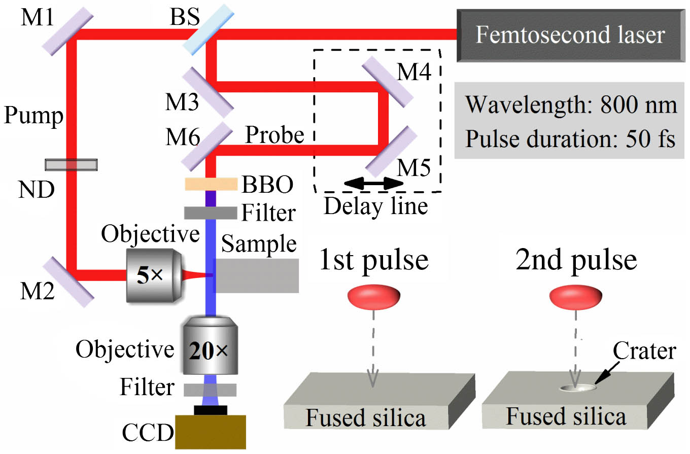
    Fig. 1. Schematic of the pump–probe experimental setup. BS, beam splitter; M, mirror; ND, variable neutral density filter.
    Time-resolved shadowgraphs of the plasma and shockwave generated by femtosecond laser irradiation on fused silica with a laser fluence of 13.75 J/cm2. (a), (b) Images recorded after the first pulse (N=1); (d), (e) images recorded after the second pulse (N=2). P indicates the protuberance on the top of the plasma and shockwave front. (c), (f) AFM morphologies of the crater cross section after the first and second pulse ablation. The red line in (c) is the parabolic curve fitting for the cross section with a radius of curvature of 44 μm.
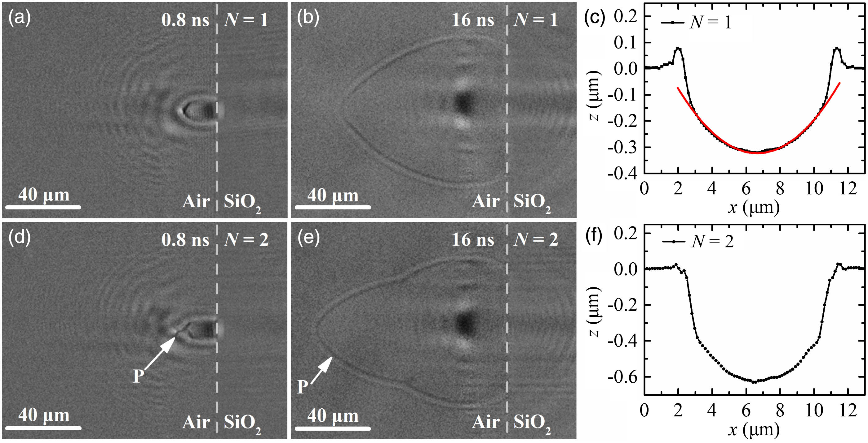
    Fig. 2. Time-resolved shadowgraphs of the plasma and shockwave generated by femtosecond laser irradiation on fused silica with a laser fluence of 13.75  J/cm2. (a), (b) Images recorded after the first pulse (N=1); (d), (e) images recorded after the second pulse (N=2). P indicates the protuberance on the top of the plasma and shockwave front. (c), (f) AFM morphologies of the crater cross section after the first and second pulse ablation. The red line in (c) is the parabolic curve fitting for the cross section with a radius of curvature of 44 μm.
    Shadowgraphs of the plasma and shockwave generated by femtosecond laser irradiation on fused silica with laser fluences of 10.8, 19.2, and 40.1 J/cm2. (a)–(c) Images recorded after the first pulse (N=1), (d)–(f) images recorded after the second pulse (N=2). P indicates the protuberance on the top of the plasma and shockwave front. The probe delay is 16 ns.
    Fig. 3. Shadowgraphs of the plasma and shockwave generated by femtosecond laser irradiation on fused silica with laser fluences of 10.8, 19.2, and 40.1  J/cm2. (a)–(c) Images recorded after the first pulse (N=1), (d)–(f) images recorded after the second pulse (N=2). P indicates the protuberance on the top of the plasma and shockwave front. The probe delay is 16 ns.
    Calculation of the refocused laser intensity. (a) Time dependence of surface reflectivity, and incident and reflected laser intensity at the beam center (x=0) during the first pulse irradiation, (b) spatial distributions of the incident and reflected laser intensity at time zero, at which the peak intensity arrives during the first pulse irradiation, (c) refocused laser intensity distribution at the refocused focal plane at time zero during the second pulse irradiation, (d) cross section of the refocused laser intensity distribution at time zero. The incident laser fluence is 13.75 J/cm2.
    Fig. 4. Calculation of the refocused laser intensity. (a) Time dependence of surface reflectivity, and incident and reflected laser intensity at the beam center (x=0) during the first pulse irradiation, (b) spatial distributions of the incident and reflected laser intensity at time zero, at which the peak intensity arrives during the first pulse irradiation, (c) refocused laser intensity distribution at the refocused focal plane at time zero during the second pulse irradiation, (d) cross section of the refocused laser intensity distribution at time zero. The incident laser fluence is 13.75  J/cm2.
    (a), (b) AFM morphology of the microlens fabricated by single femtosecond laser irradiation with a fluence of 4.5 J/cm2, followed by 5% HF etching for 90 min, (c) shadowgraph of the shockwave induced by single-pulse ablation of a concave microlens (N=1), (d) shadowgraph of the shockwave induced by the second pulse ablation of flat fused silica (N=2). The fluence is 13.75 J/cm2.
    Fig. 5. (a), (b) AFM morphology of the microlens fabricated by single femtosecond laser irradiation with a fluence of 4.5  J/cm2, followed by 5% HF etching for 90 min, (c) shadowgraph of the shockwave induced by single-pulse ablation of a concave microlens (N=1), (d) shadowgraph of the shockwave induced by the second pulse ablation of flat fused silica (N=2). The fluence is 13.75 J/cm2.
    Qingsong Wang, Lan Jiang, Jingya Sun, Changji Pan, Weina Han, Guoyan Wang, Hao Zhang, Costas P. Grigoropoulos, Yongfeng Lu. Enhancing the expansion of a plasma shockwave by crater-induced laser refocusing in femtosecond laser ablation of fused silica[J]. Photonics Research, 2017, 5(5): 488
    Download Citation