
Andrey A. Machnev, Anatoly P. Pushkarev, Pavel Tonkaev, Roman E. Noskov, Kristina R. Rusimova, Peter J. Mosley, Sergey V. Makarov, Pavel B. Ginzburg, Ivan I. Shishkin. Modifying light–matter interactions with perovskite nanocrystals inside antiresonant photonic crystal fiber[J]. Photonics Research, 2021, 9(8): 1462
- Photonics Research
- Vol. 9, Issue 8, 1462 (2021)
Abstract
1. INTRODUCTION
Controlling light–matter interaction strength is a highly important objective in many fundamental aspects of science and relevant applications. Being inherently small, the fine-structure constant is responsible for light–matter interaction dynamics and the rates of related quantum processes. However, a structured electromagnetic environment is capable of modifying and tailoring these dynamics quite significantly by introducing new interaction channels [1]. There are two main approaches to control the structure of free-space fields—the first one is to create a cavity capable of concentrating electromagnetic energy. Cavity quantum electrodynamics (CQED), having a well-understood theoretical background, keeps inspiring investigation of new effects and experimental realizations. Numerous dielectric, plasmonic, and other types of structures have been realized, uncovering various types of light–matter interactions [2–5]. The second approach to manipulate quantum processes is to increase the light–matter interaction length. A typical layout in this case relies on a waveguide, supporting a long-distance propagation of electromagnetic waves without diffraction losses [6,7].
Over the past several decades, fiber technology has progressed a long distance from the rolled fiberglass to photonic crystal fibers (PCFs). Originally, step-index optical fibers were designed for information and communications technology. However, the advent of PCFs has led to extending their applications to many other areas, while advances in additive manufacturing techniques have the potential to shift fiber technologies to new frontiers [8,9]. PCFs consist of a set of microstructured capillaries running along the entire fiber length in order to suppress light escaping from the fiber core due to a photonic bandgap (bandgap PCFs), topological effect (kagome PCFs), or negative curvature phenomenon [antiresonant PCFs (AR-PCFs)]. Low optical losses and a large analyte–light interaction volume have stimulated using PCFs in such realms as photochemistry, optomechanics, biomedical and chemical sensing, and many others [10–12].
In order to increase the interaction strength between an analyte and propagating modes in a solid-core fiber, the jacket can be removed and leaking near fields are made accessible. However, a configuration where a field inside the fiber core overlaps with the matter suggests significant improvement of the interaction strength. It has been shown that hollow-core fibers can be used as spectrofluorimetric systems in which sample solutions are excited within the microstructure of the fiber [13–15]. Another notable spectrum of PCF applications can be achieved via functionalization of the fiber inner structure. For example, deposition of composite materials on the inner surface of PCF’s structure can tune the fiber light guiding properties in a controllable fashion [16,17]. Hence, comprehensive studies of factors affecting light–matter interaction dynamics inside a fiber could enable further advances in the field.
Sign up for Photonics Research TOC. Get the latest issue of Photonics Research delivered right to you!Sign up now
In our work, we use a so-called free-boundary AR-PCF [Fig. 1(a)], where the dynamics of light–matter interactions are governed by two main factors. The first factor is the propagation of light along the fiber. The second one is the transverse confinement, associated with the design of the internal structure. In order to probe those mechanisms, we have deposited halide perovskite nanocrystals on the fiber capillary walls and investigated the impact of the fiber structure on their fluorescent properties, including changes in the emitted light intensity and fluorescence lifetime.
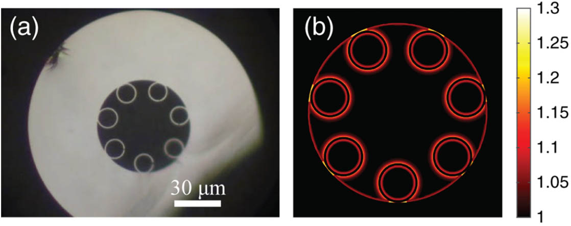
Figure 1.(a) Optical micrograph of an AR-PCF cross section. (b) Orientation-averaged Purcell enhancement map as a function of emitter position inside the fiber, obtained by the FEM simulations.
2. NUMERICAL SIMULATIONS
A. Purcell Enhancement inside AR-PCF
The manipulation of the spontaneous emission rate of an emitter via modification of the surrounding electromagnetic environment is known as the Purcell effect [18]. The radiation Purcell factor is defined as the ratio between the decay rates in a structure and the free-space value . This ratio is directly linked to the local electromagnetic field and enables probing the latter by investigating the fluorescent properties of light emitters [19]:
It is quite remarkable that the classical-quantum correspondence principle, based on a local Langevin quantization, allows the calculation of spontaneous decay rates and other higher-order phenomena with classical electrodynamic tools (e.g., Refs. [1,20,21]). In fact, the calculation of in Eq. (1) can be obtained with a numerical modeling, which can be implemented in a number of commercially available packages. While Eq. (1) addresses a hypothetical case of a perfect emitter with a quantum yield equal to unity, nonradiative channels can be introduced to the formalism phenomenologically. Considering the balance between the radiated and dissipated energies and assuming a weak coupling regime with radiative decay dynamics described with a single exponential contribution [22] , the overall Purcell factor can be written as
B. Modes of AR-PCF
The fiber modes have been calculated by a finite element method (FEM). They can be divided into two groups: cladding or leaky modes and core (guided) modes. In our work we consider the fundamental core mode () and a mixture of cladding modes. Numerically calculated core and cladding mode field distributions and their effective indices are shown in Figs. 2(a) and 2(b). Experimentally, the fundamental mode was excited by overlapping a weakly focused Gaussian beam at a wavelength of 485 nm with the fiber core, while leaky modes were excited by shifting the beam to the fiber cladding. Due to the short fiber length (several centimeters), these modes were detected with a CCD camera from the output fiber facet [Figs. 2(c) and 2(d)] (additional experimental details will be provided hereinafter). The resulting interference is the result of the excitation of a set of leaky modes, which have different mode profiles with very close effective indices. The calculated effective index has a real part close to 1.4499. Since fundamental and leaky modes are spatially well separated, they can be probed individually by spatial filtering in the image plane.
![]()
Figure 2.Numerically calculated field distribution of (a) core LP01 and (b) cladding modes. Microphotographs of the output fiber facet, revealing coupling to (c) core mode and (d) cladding modes. Discrepancies between numerical results and experimentally observed distributions occur owing to multiple cladding modes’ interference.
Spontaneous emission rate is inversely proportional to the group velocity [24], and when the modal dispersion is negligible it grows linearly with the modal effective index. Consequently, a higher mode index for the cladding modes is expected to result in a higher Purcell factor compared to the case of the guided core mode with a near-unity effective index.
3. EXPERIMENTAL METHODS
A. Perovskite Nanocrystal Synthesis
nanocrystals (NCs) were synthesized by using similar procedures reported by Protesescu
B. AR-PCF Fabrication
The photonic crystal fiber was fabricated at the University of Bath using the stack-and-draw technique [26]. Hollow silica capillaries are placed inside a silica jacket tube and supported by additional glass tubes at either end, creating a preform containing a single ring of seven separate capillaries around a hollow core. This preform is then drawn to fiber via an intermediate cane stage in which the capillaries become fused to the jacket. In the final draw stage differential pressure is applied to the core and the capillaries to yield control over the degree of inflation and hence the dimensions of the cladding structure. Thus, we create fiber in which the thickness of the single silica layer adjacent to the core is very well controlled and supports guidance of core modes in wavelength ranges that are in antiresonance with the core–cladding boundary [27]. The AR-PCF used in this work has a core size of approximately 30 μm, capillaries 12 μm in diameter, and a cutback measurement over 60 m of fiber reveals a transmission window around 600 nm wavelength with attenuation below 0.25 dB/km between 550 and 650 nm. The short length of AR-PCF used in the experiments presented here enables transmission over a slightly broader wavelength range.
C. Deposition of Perovskite Nanocrystals inside AR-PCF
The AR-PCF was glued into the syringe needle using mounting wax (Apiezon W Wax). The needle with the fiber glued inside was attached to a luer syringe filled with solvent or particle suspension, and constant pressure was applied. The perovskite quantum dots were deposited inside the AR-PCF using a two-step process. First, the fiber was washed with toluene for 1 h in order to improve adhesion of perovskite dots to the fiber surface. Second, the particle solution in dimethyl formamide was rinsed through the fiber for 30 min. After the perovskite crystal deposition, the fiber was flushed with dimethyl formamide for 30 min to remove excess crystals, and the fiber was put on hotplate at 100°C for 2 h to remove excess solvent from the fiber core. After the dots’ deposition, both ends of the capillary were cleaved to avoid crystalline deposits on the fiber facets.
The deposited perovskite NCs inside the AR-PCF were characterized by SEM and confocal scanning laser microscopy (CLSM) as shown in Fig. 3. It is noteworthy that there were no large clusters of perovskite nanoparticles, and the perovskite nanoparticles were located on all capillary surfaces with the size of individual crystals ranging between 20 and 50 nm.
![]()
Figure 3.(a) SEM image of the inner fiber capillary. (b) Zoomed view of the capillary sidewall. (c) CLSM cross section of the fiber section. (d) 3D reconstruction of the CLSM data plotted as iso-intensity surfaces.
CLSM data was obtained using a Leica DM8 microscope with a objective (NA = 0.75). The excitation was performed at 488 nm, and the fluorescence was detected with the filter set to a 505–530 nm window. The cleaved AR-PCF was mounted on a holder to measure a -stack. Figure 3(c) shows a single cross section of the acquired stack. It can be seen that the fluorescence intensity distribution varies between individual capillaries, which can be caused by constrained flow of the solution in one of the smaller capillaries. The three-dimensional reconstruction of perovskite fluorescence also shows that one of the capillaries has significantly smaller filling fraction of emitters [Fig. 3(d)].
It should be noted that lack of aggregates justifies the use of suggested analytical model for Purcell factor assessment—the individual crystals are well separated from each other and small enough to be considered as point radiation sources.
D. Optical Characterization Setup
A schematic of the experimental setup is depicted in Fig. 4. The spectrally filtered supercontinuum laser (YSL SC Pro with VLF filter, excitation band 480–490 nm) is coupled to the AR-PCF with perovskite quantum dots with a objective. The excitation power was attenuated to levels, when the shape of the lifetime curve of the dots was not changed. The light was outcoupled from fiber using a objective, the excitation was suppressed using a 500 nm longpass filter (Semrock), and background rejection was improved using a spatial filter (1:1 telescope with 200 μm pinhole in the focal plane). The fiber facet was imaged using an lens and split by a 50:50 beam splitter between the CMOS camera and the fiber-coupled spectrometer (Andor Kymera 193) with a single-photon counter (MicroPhotonDevices). The lifetimes were obtained using time-tagging electronics (TimeHarp 260, Picoquant) and analyzed using dedicated software (Fluofit, Picoquant).
![]()
Figure 4.(a) Schematic of the experimental setup. Filtered supercontinuum light source is coupled to a fiber under test. (b) Positions of the collection points in experiment (1) core, (2) ring, and (3) cladding.
4. RESULTS
Time-correlated single-photon counting was employed to measure lifetime changes of perovskite NCs deposited on the fiber capillaries. The experimental layout appears in Fig. 4(a) and contains two main parts—coupling of excitation light into the PCF and collection of the transmitted light. The output fiber facet is imaged with the objective, and perovskite NCs emission is analyzed. Optical signals were collected with a fiber mounted on a motorized stage. The aperture of the collection fiber acts as a spatial filter, which enables assessing the contribution of different modes to the overall interaction phenomenon.
Lead halide perovskite NCs were chosen for the experiment. Such materials have chemical formula , where (cation) stands for organic or inorganic cations, is lead, and is replaced by I, Br, or Cl. Distinct features of lead halide perovskites are pronounced exciton resonance at room temperature and high quantum yield, which make them good candidates for probing local Purcell enhancement. By changing the anion composition, it is possible to tune the emission wavelength over the whole visible spectrum. Here the crystals were chosen to fit the transparency window of the fiber.
The impact of the AR-PCF modes hierarchy on the emission properties was analyzed by measuring the photoluminescence and luminescence decay rates of perovskite NCs. The schematic of the measurements is depicted in Fig. 4(a). The excitation light was coupled to AR-PCF, and the emission of the perovskite NCs was analyzed at different points at the AR-PCF cross section [Fig. 4(b)]: (1) core of AR-PCF, (2) capillary of AR-PCF, and (3) fiber cladding near the surface of the inner capillary. The fiber capillaries and core were flushed with toluene to improve adhesion of the perovskite NCs to the fiber glass.
Photoluminescence was excited by using a band-filtered supercontinuum light source centered around 470 nm with bandwidth of 10 nm. In order to avoid pump-dependent effects, the excitation power was decreased down to levels where no pump-dependent lifetime shortening was observed. The collected signal was spectrally filtered with a longpass filter to suppress excitation light and spatially filtered with a collection fiber in order to distinguish between signals coupled into different modes in the fiber.
Since the Purcell enhancement is position dependent [Fig. 1(b)] and the signal is collected from a large set of emitters coupled to core or cladding modes, initially a single exponential decay of an isolated nanocrystal becomes more complex, showing multiple emitters’ contributions (e.g., Refs. [28,29]). In order to account for this position and orientation dependence, decay curves were fitted using a multi-exponential model with deconvolution fitting, where an instrument response function (IRF) was used to factor in a finite duration of the pump pulse (under 150 ps) and overall delay in electronics responses. The time-dependent signal is
Spontaneous emission spectra were measured first. Figure 5(a) shows the data for three collection points. While the spectral shapes are similar in all cases, the emission peak center exhibits a redshift when moving the probe point away from the fiber’s center. This effect is associated with self-absorption of emitted light, which is well known in perovskite nanowires [30–32]. Time traces of the luminescence decay for the probe points appear in Figs. 5(b)–5(d), making the direct comparison possible. The lifetimes (biexponential decay) for the perovskite quantum dots [blue curve in Fig. 5(b)] deposited on the glass were and , which are in good agreement with the values for colloid-synthesized perovskite quantum dots, reported in literature [25].
![]()
Figure 5.(a) Normalized photoluminescence spectra of perovskite quantum dots inside the AR-PCF. (b) Lifetimes of quantum dots drop-cast on clean glass coverslip (reference) and measured from the core of AR-PCF (core). (c) Lifetimes of perovskite dots coupled to cladding and to the core of fiber. (d) Lifetimes of perovskite dots coupled to the capillary compared to the core of the fiber.
The first observation to be made is that the lifetime of perovskite quantum dots in the core is almost identical to the free-space scenario (the reference) as shown in Fig. 5(b). The reference measurements were taken by depositing a thin layer of perovskite dots on cleaned glass coverslip and by averaging over 10 measurements. This is fully consistent with both the modal and local Purcell approach, suggesting the enhancement to be negligible (close to unity). The shortest luminescence lifetime emerges from the emission coupled to the cladding modes as seen in Figs. 5(c) and 5(d).
In order to distinguish the difference between emission of quantum dots coupled to cladding modes and free-space emission, we calculate both intensity and amplitude-weighted lifetimes. The lifetimes at different points of interest on the fiber and of reference perovskite dots are summarized in Table 1. Here, for the sake of simplicity, we consider a multi-exponential decay model, where emission decay is described by Eq. (1). However, it should be noted that the more accurate description of charge-carrier recombination dynamics is given by the ABC model, which factors in multiple-particle recombination effects [33]. Summary on Lifetime Data Extracted from PL Decay CurvesReference 3.75 2.51 Core 4.09 2.72 Capillary 2.81 1.4 Cladding 2.72 0.82
The analysis of the impact of the Purcell effect on quantum dot emission was carried out for averaged values of lifetimes [34], intensity-weighted and amplitude-weighted, which are described with the following relations:
Following Ref. [35], intensity-weighted lifetimes are used for the Purcell factor analysis owing to their lower sensitivity to the fitting model.
Table 2 summarizes the values of Purcell factor calculated for different modes, propagating in the fiber. The lowest value is observed for the core-coupled modes, yielding value of . The cladding modes exhibit higher values of Purcell factor of (for the modes outcoupled from inner capillary structure) and (for the modes outcoupled from cladding). The obtained values are in good agreement with numerical simulation result for the quantum dots located in the vicinity of the capillaries. Purcell Factors for Different Modes of the FiberP Reference 3.75 Core 4.09 0.92 Capillary 2.81 1.33 Cladding 2.72 1.38
Finally, it is worth making the comparison between the local Purcell effect analysis and the modal structure. The latter approach uses an effective index as a single input parameter. Indeed, the modal description predicts no enhancement for emitters in the core and 1.45 for those coupled to the cladding. Comparing the results, it can be seen that both approaches agree with each other within , nevertheless local Purcell analysis provides a better fit. This result demonstrates the impact of local structuring over the global response of the system. It is worth noting that the computational complexity favors the modal approach by far (a single 2D simulation versus a large number of full-wave 3D computations). Similar conclusions were drawn by expecting local interactions with, e.g., metamaterials [36,37].
5. CONCLUSIONS AND OUTLOOK
Here we have compared those two approaches by investigating spontaneous emission processes inside an AR-PCF, functionalized with perovskite crystals. Hollow-core photonic crystal fibers, supporting long-distance light propagation inside a hollow capillary, have a rather complex internal structure. The latter complicates studies of light–matter dynamics of processes occurring inside the fiber. While local Langevin quantization of electromagnetic fields allows addressing interaction processes of any order, the modal description of propagation has a clear advantage of providing an intuitive description. Spontaneous emission, being the first-order quantum process, allows probing the local density of states, which is one of the key input parameters in any quantum model. Applying spatial filtering on a collected signal together with time-correlated single-photon counting, we reconstructed local Purcell enhancement in the fiber and compared it qualitatively with the effective index of core and cladding modes, which predicts higher Purcell enhancement for cladding modes. We found that local approach agrees with the experimental data within and correlates with estimates. Local Purcell analysis demonstrates the impact of local structuring over the global response of the system and allows assessment of enhancement value qualitatively.
References
[1] W. Vogel, D. Welsch. Quantum Optics(2006).
[2] K. J. Vahala. Optical microcavities. Nature, 424, 839-846(2003).
[3] S. M. Dutra. Cavity Quantum Electrodynamics(2004).
[4] P. Ginzburg, A. V. Krasavin, A. N. Poddubny, P. A. Belov, Y. S. Kivshar, A. V. Zayats. Self-induced torque in hyperbolic metamaterials. Phys. Rev. Lett., 111, 036804(2013).
[5] P. Ginzburg. Cavity quantum electrodynamics in application to plasmonics and metamaterials. Rev. Phys., 1, 120-139(2016).
[6] B. Kannan, M. J. Ruckriegel, D. L. Campbell, A. F. Kockum, J. Braumüller, D. K. Kim, M. Kjaergaard, P. Krantz, A. Melville, B. M. Niedzielski, A. Vepsäläinen, R. Winik, J. L. Yoder, F. Nori, T. P. Orlando, S. Gustavsson, W. D. Oliver. Waveguide quantum electrodynamics with superconducting artificial giant atoms. Nature, 583, 775-779(2020).
[7] D. E. Chang, A. S. Sørensen, E. A. Demler, M. D. Lukin. A single-photon transistor using nanoscale surface plasmons. Nat. Phys., 3, 807-812(2007).
[8] L. A. van der Elst, L. A. van der Elst, M. G. Kurtoglu, T. Leffel, M. Zheng, A. Gumennik. Rapid fabrication of sterile medical nasopharyngeal swabs by stereolithography for widespread testing in a pandemic. Adv. Eng. Mater., 22, 2000759(2020).
[9] C. Markos, J. C. Travers, A. Abdolvand, B. J. Eggleton, O. Bang. Hybrid photonic-crystal fiber. Rev. Mod. Phys., 89, 045003(2017).
[10] A. Gumennik, A. M. Stolyarov, B. R. Schell, C. Hou, G. Lestoquoy, F. Sorin, W. McDaniel, A. Rose, J. D. Joannopoulos, Y. Fink. All-in-fiber chemical sensing. Adv. Mater., 24, 6005-6009(2012).
[11] J. F. Algorri, D. C. Zografopoulos, A. Tapetado, D. Poudereux, J. M. Sánchez-Pena. Infiltrated photonic crystal fibers for sensing applications. Sensors, 18, 4263(2018).
[12] T. Ermatov, R. E. Noskov, A. A. Machnev, I. Gnusov, V. Atkin, E. N. Lazareva, S. V. German, S. S. Kosolobov, T. S. Zatsepin, O. V. Sergeeva, J. S. Skibina, P. Ginzburg, V. V. Tuchin, P. G. Lagoudakis, D. A. Gorin. Multispectral sensing of biological liquids with hollow-core microstructured optical fibres. Light Sci. Appl., 9, 173(2020).
[13] A. M. Cubillas, S. Unterkofler, T. G. Euser, B. J. M. Etzold, A. C. Jones, P. J. Sadler, P. Wasserscheid, P. St.J. Russell. Photonic crystal fibres for chemical sensing and photochemistry. Chem. Soc. Rev., 42, 8629-8648(2013).
[14] G. O. S. Williams, T. G. Euser, P. St.J. Russell, A. J. MacRobert, A. C. Jones. Highly sensitive luminescence detection of photosensitized singlet oxygen within photonic crystal fibers. ChemPhotoChem, 2, 616-621(2018).
[15] G. O. S. Williams, T. G. Euser, P. St.J. Russell, A. C. Jones. Spectrofluorimetry with attomole sensitivity in photonic crystal fibres. Methods Appl. Fluoresc., 1, 015003(2013).
[16] T. Ermatov, Y. V. Petrov, S. V. German, A. A. Zanishevskaya, A. A. Shuvalov, V. Atkin, A. Zakharevich, B. N. Khlebtsov, J. S. Skibina, P. Ginzburg, R. E. Noskov, V. V. Tuchin, D. A. Gorin. Microstructured optical waveguide-based endoscopic probe coated with silica submicron particles. Materials, 12, 1424(2019).
[17] R. E. Noskov, A. A. Zanishevskaya, A. A. Shuvalov, S. V. German, O. A. Inozemtseva, T. P. Kochergin, E. N. Lazareva, V. V. Tuchin, P. Ginzburg, J. S. Skibina, D. A. Gorin. Enabling magnetic resonance imaging of hollow-core microstructured optical fibers via nanocomposite coating. Opt. Express, 27, 9868-9878(2019).
[18] E. M. Purcell. Proceedings of the American physical society. Phys. Rev., 69, 37-38(1946).
[19] L. Novotny, B. Hecht. Principles of Nano-Optics(2006).
[20] A. N. Poddubny, P. Ginzburg, P. A. Belov, A. V. Zayats, Y. S. Kivshar. Tailoring and enhancing spontaneous two-photon emission using resonant plasmonic nanostructures. Phys. Rev. A, 86, 033826(2012).
[21] I. V. Iorsh, A. N. Poddubny, P. Ginzburg, P. A. Belov, Y. S. Kivshar. Compton-like polariton scattering in hyperbolic metamaterials. Phys. Rev. Lett., 114, 185501(2015).
[22] L. D. Landau, L. D. Landau, E. M. Lifshitz, E. M. Lifshitz. Chapter IX—The electromagnetic wave equations. Electrodynamics of Continuous Media, 8, 257-289(1984).
[23] A. E. Krasnok, A. P. Slobozhanyuk, C. R. Simovski, S. A. Tretyakov, A. N. Poddubny, A. E. Miroshnichenko, Y. S. Kivshar, P. A. Belov. An antenna model for the Purcell effect. Sci. Rep., 5, 12956(2015).
[24] V. S. C. M. Rao, V. S. Manga, S. Hughes. Single quantum-dot Purcell factor and
[25] L. Protesescu, S. Yakunin, M. I. Bodnarchuk, F. Krieg, R. Caputo, C. H. Hendon, R. X. Yang, A. Walsh, M. V. Kovalenko. Nanocrystals of cesium lead halide perovskites (CsPbX3, X = Cl, Br, and I): novel optoelectronic materials showing bright emission with wide color gamut. Nano Lett., 15, 3692-3696(2015).
[26] E. J. Allen, G. Ferranti, K. R. Rusimova, R. J. A. Francis-Jones, M. Azini, D. H. Mahler, T. C. Ralph, P. J. Mosley, J. C. F. Matthews. Passive, broadband, and low-frequency suppression of laser amplitude noise to the shot-noise limit using a hollow-core fiber. Phys. Rev. Appl., 12, 044073(2019).
[27] W. Belardi, J. C. Knight. Hollow antiresonant fibers with low bending loss. Opt. Express, 22, 10091-10096(2014).
[28] A. S. Kadochkin, I. I. Shishkin, A. S. Shalin, P. Ginzburg. Quantum sensing of motion in colloids via time-dependent Purcell effect. Laser Photon. Rev., 12, 1800042(2018).
[29] V. A. Podolskiy, P. Ginzburg, B. Wells, A. V. Zayats. Light emission in nonlocal plasmonic metamaterials. Faraday Discuss., 178, 61-70(2015).
[30] S. Zhang, Q. Shang, W. Du, J. Shi, Z. Wu, Y. Mi, J. Chen, F. Liu, Y. Li, M. Liu, Q. Zhang, X. Liu. Strong exciton-photon coupling in hybrid inorganic-organic perovskite micro/nanowires. Adv. Opt. Mater., 6, 1701032(2018).
[31] X. Wang, M. Shoaib, X. Wang, X. Zhang, M. He, Z. Luo, W. Zheng, H. Li, T. Yang, X. Zhu, L. Ma, A. Pan. High-quality in-plane aligned CsPbX perovskite nanowire lasers with composition-dependent strong exciton-photon coupling. ACS Nano, 12, 6170-6178(2018).
[32] A. P. Pushkarev, V. I. Korolev, D. I. Markina, F. E. Komissarenko, A. Naujokaitis, A. Drabavičius, V. Pakštas, M. Franckevičius, S. A. Khubezhov, D. A. Sannikov, A. V. Zasedatelev, P. G. Lagoudakis, A. A. Zakhidov, S. V. Makarov. A few-minute synthesis of CsPbBr nanolasers with a high quality factor by spraying at ambient conditions. ACS Appl. Mater. Interfaces, 11, 1040-1048(2019).
[33] R. L. Milot, G. E. Eperon, H. J. Snaith, M. B. Johnston, L. M. Herz. Temperature-dependent charge-carrier dynamics in CH3NH3PbI3 perovskite thin films. Adv. Func. Mater., 25, 6218-6227(2015).
[34] A. Sillen, Y. Engelborghs. The correct use of “average” fluorescence parameters. Photochem. Photobiol., 67, 475-486(1998).
[35] E. Fišerová, M. Kubala. Mean fluorescence lifetime and its error. J. Luminesc., 132, 2059-2064(2012).
[36] A. P. Slobozhanyuk, P. Ginzburg, D. A. Powell, I. Iorsh, A. S. Shalin, P. Segovia, A. V. Krasavin, G. A. Wurtz, V. A. Podolskiy, P. A. Belov, A. V. Zayats. Purcell effect in hyperbolic metamaterial resonators. Phys. Rev. B, 92, 195127(2015).
[37] A. A. Bogdanov, A. S. Shalin, P. Ginzburg. Optical forces in nanorod metamaterial. Sci. Rep., 5, 15846(2015).

Set citation alerts for the article
Please enter your email address
© Copyright 2018-2021 | Chinese Laser Press. All Rights Reserved 沪ICP备15018463号-20