Storage rings of the next generation synchrotron light sources have quite small dynamic apertures with which transverse beam injection can hardly be efficient. The longitudinal beam injection may be a solution to this problem. To apply a longer kicker pulse, it is necessary to increase time offset of the injected beam to the stored one by reducing RF frequency. The beam with a longer time offset will have a higher momentum deviation due to synchrotron motion, thus full injection of this method requires the storage ring to provide large enough energy acceptance and off-momentum dynamic aperture. A candidate lattice of the upgraded Shanghai Synchrotron Radiation Facility (SSRF-U) was used to nonlinearly optimize the longitudinal beam injection. With the optimal results of a series of RF frequencies, it is found that there is a critical RF frequency below which lowering frequency could not help to lengthen the kicker pulse in a given lattice. The beam injection into the SSRF-U storage ring was simulated and reached high efficiency with its critical RF frequency and optimal sextupole gradients.
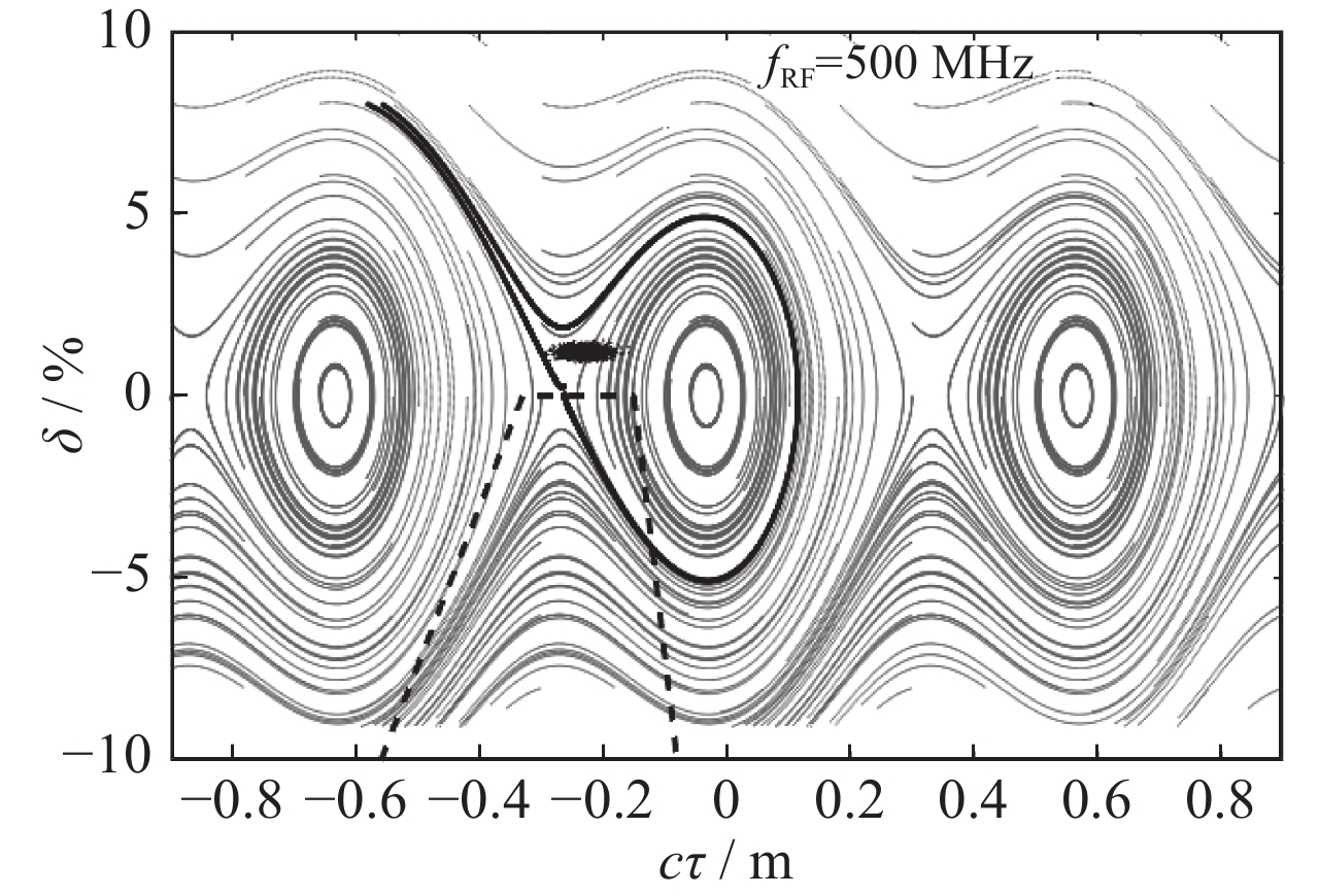
A draft of the longitudinal beam injection method is shown in Fig. 1. The abscissa of this figure uses
$c\tau $ that has a linear relation with the phase as
Synchrotron radiation light sources, serving a large number of users for scientific experiments, have been developed with three generations over the past fifty years. Electron beam emittance was reduced from hundreds of nanometer-radians to sub nanometer-radians, which was pushed by users’ increasing requirements of photon brightness and coherence. With the progress of high-gradient magnet and high-precise alignment, a medium-sized light source employing the Multi-Bend Achromatic (MBA) lattice can obtain very low beam emittance down to the X-ray diffraction limit [1-3]. However, strong chromaticity-correcting sextupoles make the MBA lattice suffer from a smaller Dynamic Aperture (DA), with which it is difficult to transversely inject the electron beam off-axis into the storage ring[4-7]. Two new injection methods which are transversely on-axis were proposed to solve the problem of small DA. The first one is the Swap-out method[8-9], in which a dipole-typed kicker is applied to not only inject a bunch or a bunch train into the storage ring but also kick the stored bunches back to an accumulation ring for reuse or out of the storage ring. Longitudinal beam injection method[10-13], the second one, uses the dipole-typed kicker to bring new beam with its time or/and momentum off from the stored beam into the storage ring. By radiation damping, the injected beam then merges with the stored one in the synchrotron phase space.
The Shanghai Synchrotron Radiation Facility (SSRF)[15-17] has an upgrade plan to reach the soft X-ray diffraction limit. The upgraded facility is named as SSRF-U. This paper takes a candidate lattice of the SSRF-U storage ring as example to present the nonlinear optimization strategy. The optimization results with different RF frequencies show whether and how it takes full advantage of the reduced RF frequency. Beam injection of the lattice was simulated with the critical RF frequency and the optimal harmonic sextupole gradients. All the particle tracking and simulation in this paper were implemented within the Accelerator Toolbox[18].
where c is the speed of light, τ is the time offset, fRF is the frequency of the Radio Frequency (RF) system, and
$\varphi $ is the RF phase. Shown as black points in Fig. 1, the injected beam with a time offset to the stored beam is kicked into the closed orbit after the kicker pulse rose. Full pulse of the kicker (the dash line), which includes flat rising and falling time, cannot be longer than a bucket interval in order not to disturb the stored beam. It has to be less than two nanoseconds with the RF system of 500 MHz. Technique to generate this very short pulse is a challenge in the longitudinal beam injection. A solution to this problem is to reduce the RF frequency. The time offset of the injected beam is expected to increase in this way, so that the pulse can be lengthened (to 10 ns with 100 MHz, for example). Because of the synchrotron motion, the beam with large time offset will have a high momentum deviation. In the lattice, a large energy acceptance is required for efficient beam injection. Enough off-momentum DA of the lattice, usually several times of the injected beam size, is necessary to capture all the particles. At the same time, tune with high momentum deviation should be controlled away from the linear resonances[14]. A careful nonlinear optimization for the lattice is necessary to get these good performances.
1 Lattice of the SSRF-U storage ring
As new light sources with lower beam emittance and higher photon brightness have been successfully operated and many more light sources are conducting their research and development to the diffraction limit[19-21], an upgrade from SSRF to SSRF-U is proposed to improve its competitiveness among these facilities. The SSRF-U will use the existing building and tunnel, as well as the straight sections and already planned insertion devices. Its performance must meet the requirement of the scientific experiments. The hybrid filling pattern (a bunch train plus a single bunch) and high-current single bunch for time-resolved experiments, for example, should also be stably operated.
Ref.[22] has presented a lattice of the SSRF-U storage ring whose beam emittance is 200 pm·rad at beam energy of 3.0 GeV. Thanks to the horizontal on-momentum DA of this lattice being about 8 mm, the traditional beam injection method based on orbit bump is reliable. This paper presents a new candidate lattice with the natural emittance reduced down to 97 pm·rad without the effect of intro-beam scattering. It nearly reaches the soft X-ray diffraction limit, but only a small on-momentum DA of about 3 mm has been got. The new lattice consists of 20 seven-bend-achromat (7BA) cells with four-fold symmetry. Each cell has seven dipoles, 12 quadrupoles, and 12 sextupoles. The maximum gradients are 80 T/m in the quadrupoles and 7000 T/m2 in the sextupoles. The horizontal and vertical tunes were chosen to be 61.22 and 15.32, away from the harmful nonlinear resonances. Beam parameters of the ring are summarized in Table 1 and beam optics in one fold are plotted in Fig. 2. The lattice provides four long straight sections with length of 10.84 m and sixteen short straight sections with 5.57 m length. Injection system will be installed in one of the long straight sections, of which the center with horizontal and vertical β functions of 12 m and 5 m is the injection point. The horizontal and vertical β functions at the center of a short straight section are 5 m and 2.5 m respectively.
lattice
20×7BA
beam energy/GeV
3.0
circumference/m
432
tune (H, V, S)
61.22, 15.32, 0.001 64
natural chromaticity (H, V)
−129.2, −81.04
corrected chromaticity (H, V)
2.0, 2.0
momentum compaction factor
0.000 1
damping partition number (H, V, S)
1.374, 1.000, 1.626
damping time (H, V, S)/ms
12.29, 16.89, 10.39
energy loss per turn/keV
512.0
natural energy spread
7.616×10⁻⁴
natural emittance/(pm·rad)
97.00
RF voltage/MV
1.50
Table 1. The lattice parameters of the SSRF-U storage ring
The RF voltage will modify the synchrotron phase space, and thus influence the longitudinal beam injection. A given momentum deviation usually corresponds longer time offset if the RF voltage is reduced. So it is better to use low voltage for lengthening the kicker pulse. However, the voltage cannot be too low to compensate the radiation loss from the dipoles and all the possible insertion devices. It was fixed by a tradeoff to be 1.5 MV in the SSRF-U storage ring.
2 Nonlinear optimization
The SSRF-U storage ring has six harmonic sextupoles in each cell to cancel high order aberrations. All the harmonic sextupoles were classified into nine families based on the periodicity of beam optics. Nonlinearity of the storage ring was optimized by these harmonic sextupoles, meanwhile the chromaticities in both transverse planes were always corrected to two by the sextupoles in the arc sections. Many nonlinear optimization methods are effective in lattice design and machine operation[23-25], while a direct method was applied here. The harmonic sextupole gradients were randomly varied to reach the optimal solutions generation by generation. Two tracked penalty functions guided the solution choice in every generation.
The energy acceptance or the full height of the bucket that always obtained a finite DA was the first penalty function. The size of the finite DA was determined to be around five times of the injected beam size, which is expected to capture most of all the particles in the injected beam. In this way, the energy acceptance is the one available for full beam injection. The following expression Eq. (2) with the beam parameter of the booster and the beam optics at the injection point in the storage ring can calculate the injected beam size, when the electron transport line matches well with the storage ring.
where
$\varepsilon $ is the beam emittance, δE is the energy spread, and
$\eta $ is the dispersion. The horizontal and vertical β functions at the injection point are 12 m and 5 m respectively, and the dispersions are zero. Emittance of the injected beam, here from a new designed booster for SSRF-U, is 10 nm·rad. Transverse beam coupling is 10%. Beam energy spread is 0.1%, and the bunch length is 20 mm. The particles normally distribute in a bunch. These assumptions about the injected beam will be applied throughout the paper. The calculated beam sizes were about 0.33 mm and 0.07 mm in horizontal and vertical planes, so the finite DAs were set to 1.5 mm and 0.5 mm. For every setting of the harmonic sextupole gradients, the DAs of both positive and negative momentum deviations were then found out by 6-Dimension (6-D) particle tracking. The number of turns tracked was 3000, which is about one third of the circulating turns within a damping time. The upper and lower limits of the momentum deviations were recorded until the horizontal or the vertical DA was smaller than 1.5 mm or 0.5 mm. Difference between the last positive and negative value was the energy acceptance of this harmonic sextupole setting.
The horizontal and vertical tunes as a function of the momentum were then calculated within this energy acceptance. The larger tune variation amplitude in the two transverse planes was the second penalty function, which was desired to be small enough to prevent crossing the linear resonances. However, the smallest one is not the best. It is more suitable to find a distribution of the maximum energy acceptance within a range of the tune variation amplitude. Because of a large amount of the population there were too many different tune variation amplitudes in every generation, which created redundancy in parent choices in the optimization process. So within every slice of the tune variation amplitude with the width of 0.01, the sextupole solution with the maximum energy acceptance was selected as the parent solution for the next generation. To produce new population, the nine harmonic sextupole gradients of the parent solutions varied randomly within a range that decreased generation by generation. The particle tracking and the solution selection were then done again. When there was not any better solution, the optimization process ended. Fig. 3 shows the results, running dozens of generations. The RF frequency in the lattice was 100 MHz. Solutions with the tune variation amplitudes higher than 0.6 were not shown.
Figure 3.The available energy acceptance as a function of the amplitude of the tune variation with momentum
The energy acceptance significantly increases generation by generation, and eventually reaches a maximum value of about 13% (from −7% to 6%) within the tune variation amplitude from 0.2 to 0.5. Unfortunately, it is impossible to get an energy acceptance of about 20%, with which the lattice provides the longest time offset by taking full advantage of the RF frequency of 100 MHz. The same optimization processes were repeated with different RF frequencies. The results are very similar with Fig. 3 when the frequency is less than 250 MHz, while worse from 250 to 500 MHz because of the limit of the bare bucket. It is desired to increase the pulse length and get an applicable rising, falling, and flat time within a single pulse by reducing the RF frequency. A larger energy acceptance is desired for a lower RF frequency. However, the energy acceptance for full injection is limited in a given lattice with the optimal beam optics.
3 RF frequency choice
The lattices with 12 different RF frequencies (from 100 MHz to 500 MHz) were optimized by the method described above. Their optimal harmonic sextupole gradients were obtained as well as the maximum energy acceptances. The maximum time offsets (distances) of the fully injected beam to the stored beam were determined by a scanning process in the synchrotron phase space (an example can be found in the next section). For every RF frequency, the time offset and the energy deviation of the center of the injected beam were scanned within an appropriate range. The injection efficiency on every scanning grid was obtained by 3000-turn 6-D tracking of 2000 particles normally distributed in the injected beam. The maximum time offset (distance) with the injection efficiency higher than 90% was found out for every RF frequency as shown in Fig. 4.
Figure 4.The maximum distance of the fully injected beam to the stored beam as a function of the RF frequency
The distance increases when RF frequency is reduced from 500 MHz to 250 MHz, because the energy acceptance is dominated by the synchrotron motion and less than the effect of the nonlinear optimization. The distance doesn’t increase any more with RF frequency less than 250 MHz, as the energy acceptance has been limited by insufficient off-momentum DA. The synchrotron phase space will be distorted by radiation damping to show a golf-club shape (the black line in Fig. 1). There may be a stable part with positive energy deviations after an unstable point. The beam may be injected in the ring at this part. However, it should be noted that the golf-club somewhere was too narrow to accept the whole injected beam with the bunch length of 20 mm and the energy spread of 0.1% in our case. In general, the golf-club is narrower when the time offset is larger. If the time offset is too large, the full beam injection does not exist anymore. Due to the high energy deviation the part after unstable point becomes unavailable for beam injection, so it decreases with the RF frequency of about 180 MHz. When the RF frequency is 100 MHz, the distance between the fully injected beam and the stored beam is less than 0.6 m. It means that the sum of the rising and flat time of the kicker pulse must be less than 2.0 ns, which is just below expectations of 100 MHz. From these results it can be found that there is a critical RF frequency, less than which the maximum distance (or available time offset) can’t increase. The sum of rising and flat time in a single kicker pulse should be equal to or a little longer than this available time offset. If the pulse rises fast enough, it can get enough time to fall within the left of a bucket interval. It means that the required kicker pulse can’t lengthen any more by reducing the RF frequency when it is below the critical value. The critical RF frequency for the longitudinal beam injection in SSRF-U is 250 MHz as shown in Fig. 4. The possible kicker pulse is just lengthened to 4 ns. It only reduces a little hardware difficulty in view of the kicker strength.
4 An optimal solution for SSRF-U
The SSRF-U lattice performances with its critical RF frequency and optimal harmonic sextupole gradients were simulated. Fig. 5 shows the fractional tunes as functions of momentum deviation and the on- and off-momentum DAs. The tune variation is effectively suppressed. The DAs are not less than 1.5 mm and 0.5 mm in the horizontal and vertical plane respectively. They are smaller than that of the 3rd generation light source, while sufficient to fully inject beam with the longitudinal injection method.
Figure 5.Fractional tunes as functions of momentum deviation (top) and on- and off-momentum DAs (bottom)
Fig. 6 plots the simulated injection efficiency as a function of the center position of the injected beam in the synchrotron phase space. The bottom figure is an enlarged drawing of a fraction. The injected beam consists of 2000 particles. If the abscissas of particles and recirculating beam are larger than − 0.2 m, they were considered as loose. The center position of the stored beam is about − 0.07 m (synchrotron phase). The results show that if the center position of the injected beam is from − 0.6 m to − 0.7 m and the energy deviation is about 4%, full injection can be implemented in the SSRF-U storage ring. The required time of the rising and the flat in the kicker pulse can be as short as 2 ns, not including the falling time.
Figure 6.Injection efficiency as a function of the center position of the injected beam in the synchrotron phase space (shown as contour maps)
A candidate lattice of the SSRF-U storage ring with the beam emittance of 97 pm·rad has approached the soft X-ray diffraction limit. A nonlinear optimization method was applied in this lattice. The optimal results showed that this method can significantly increase the energy acceptance available for full longitudinal beam injection. However, the energy acceptance of about 13% cannot permit lengthening the kicker pulse to 10 ns with the RF frequency of 100 MHz. The lattices with a series of RF frequencies were individually optimized and could not get any higher energy acceptance. The time offset of the fully injected beam to the stored beam was determined by beam injection simulation for every tested RF frequency. With these results, the critical RF frequency reaching the maximum time offset was found to be 250 MHz in SSRF-U. The lattice with the critical RF frequency and the corresponding harmonic sextupole gradients takes full advantage of the reduced RF frequency and makes the kicker pulse lengthen doubly. Full injection can be realized in the SSRF-U storage ring when the injected beam is in a large region of the synchrotron phase space. It is necessary to note that the performances of the lattice and the volume of the injected beam dominate the critical RF frequency and the maximum time offset. Their specific values may be variable in different light sources.
Acknowledgements: The authors would like to thank Prof. Q. B. Yuan for fruitful discussions.