We propose a switchable multi-wavelength erbium-doped fiber laser based on a four-mode fiber Bragg grating (FBG). The four-mode FBG is fabricated in a hydrogen pre-loaded fiber by the phase mask method, which can support four linearly polarized modes around 1550 nm. The five operation wavelengths are at 1547.5, 1546.8, 1546.0, 1545.1, and 1544.2 nm, respectively. Through adjusting the polarization state and the lateral offset coupling in cavity, the laser can be switched into the operation state of single, dual, or triple wavelengths. The proposed laser has the advantages of simple configuration, stable operation, and easy adjustment.
Multi-wavelength fiber lasers have been widely applied in optical wavelength-division multiplexing systems[1], fiber sensors[2], terahertz-wave generation[3], and four-wave mixing[4]. It is difficult to realize stable multi-wavelength operation in erbium-doped fiber lasers (EDFLs) due to the large homogeneous line broadening of an erbium-doped fiber (EDF), leading to strong longitudinal-mode competition. Several methods have been reported to achieve stable multi-wavelength operation. Cooling an EDF to cryogenic temperature is often used to reduce the longitudinal-mode competition[5], but it is not suitable for practical applications. Other methods focused on the improvement of inhomogeneous broadening in an EDF, using an erbium-doped twin-core fiber[6], elliptical-core EDF[7], acousto-optic frequency shifter[8], multi-mode fiber[9] (MMF), and so on. As an ideal wavelength selection component for fiber lasers due to the unique advantages of fiber compatibility, ease of use, and low cost, fiber Bragg gratings (FBGs) written in a single-mode fiber (SMF) have been utilized to realize multi-wavelength oscillations through various techniques, such as cascaded FBG cavities[10,11], inline topology FBG[12], FBGs written in birefringent fiber[13], and sampled FBGs[14]. The FBGs formed in the few-mode (FM) and MMFs show multiple peaks in the reflection spectrum and have been utilized as cavity reflectors to generate multi-wavelength lasing with more simplified structures[15–18]. Han et al. demonstrated a multi-wavelength Raman fiber laser based on the FM-FBGs[15]. Yang et al. used an FM-FBG to realize a high power dual-wavelength fiber laser at 1060 nm with maximum output power of 5.67 W[16]. Su et al. used a multi-mode FBG to implement a wavelength-switching EDFL at 31 discrete wavelengths[18]. FM-FBGs have also been used in cylindrical vector beams generation and transversal-modes selection[19–22].
In this Letter, we demonstrate a fiber laser that operates at five wavelengths by employing an FM-FBG to perform the wavelength selecting function. The five oscillating wavelengths are at 1547.5, 1546.8, 1546.0, 1545.1, and 1544.2 nm, respectively. The FM-FBG was fabricated in a hydrogen pre-loaded fiber by the phase mask method in a four-mode fiber. Through adjusting the polarization and the lateral offset coupling between the SMF and the few mode fiber (FMF) in cavity, the laser can work between different operations as a single wavelength, dual interfacing wavelengths, dual divided wavelengths, or triple interfacing wavelengths with high side-mode suppression ratio (SMSR).
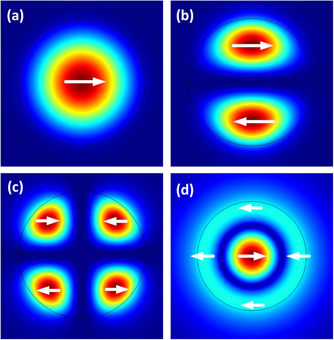
The FM-FBG used in this work was fabricated in a hydrogen pre-loaded four-mode fiber by the phase mask method and UV writing technique. The core and cladding diameters of the four-mode fiber are 19 and 125 μm, respectively. The numerical aperture (NA) is 0.12. The fiber can support four linearly polarized (LP) modes around 1550 nm. The four modes are the mode (defined as the first-order mode), mode (defined as the second-order mode), and and modes (defined as the third-order modes), respectively. The transversal electrical field distribution is analyzed by the full-vectorial mode solver technique, as shown in Fig. 1. The fundamental mode is limited in the central region, and the higher-order modes are mostly limited in the edge region, even permeating into the cladding area.
Sign up for Chinese Optics Letters TOC. Get the latest issue of Chinese Optics Letters delivered right to you!Sign up now
Figure 1.Transversal electrical field distribution of (a) , (b) , (c) , and (d) modes. The arrows indicate the polarization state.
Figure 2(a) shows the experimental setup for the measurement of the FM-FBG reflection spectrum. An amplified spontaneous emission (ASE) was used as the broadband light source, which was launched into the FM-FBG through a 3 dB coupler. The SMF and FMF were aligned by a fusion splicing connection with suitable lateral displacement. The offset splicing can achieve efficient mode coupling between the fundamental and high-order modes. The reflected light was received by an optical spectrum analyzer (OSA, ANDO AQ6317B) to measure the reflection spectrum of the FM-FBG, as shown in Fig. 2(b). In Fig. 2(b), there are five peaks in the spectrum corresponding to the five coupling wavelengths between the different modes. According to Ref. [23], the power reflection between two modes in an FM-FBG can be described by with where is the grating length, is the constant period of the FBG, is the transversal distribution of the average refractive index variation in one FBG period, is the refractive index modulation ratio along the axis, and is the propagation constant of the incident and reflected modes. In the case of step-index FMF, of the different-order modes can be approximately described as[24]where is the reflective index of the fiber core, is the normalized frequency, is the maximum relative index difference of the FMF, and is the order of the principal mode. According to Eqs. (1)–(4), the high reflection peaks appear at particular wavelengths when the phase matching condition is satisfied between the same-order modes or between the neighbor modes. If the mode order difference between two eigen modes is larger than one, the dc and ac coupling constants ( and ) are small because of the significantly smaller electrical field overlap; thus, the reflection between them can be ignored. The propagation constants of , , and modes are calculated using the step-index fiber mode theory, as shown in Fig. 2(c). When the grating period is set at 536.7 nm, the experimental results match with the theoretical analysis very well. From the analysis above, the mode reflection of the five peaks can be confirmed. In Fig. 2(b), peak 1 is for the first to first-order mode reflection, peak 2 is for the first to second-order mode reflection, peak 3 is for the second to second-order mode reflection, peak 4 is for the second to third-order mode reflection, and peak 5 is for the third to third-order mode reflection. The reflection wavelength of the fundamental to fundamental mode is at 1547.5 nm.
Figure 2.(a) Experimental setup for the measurement of reflection spectra of the FM-FBG. Black line shows the SMF and blue line shows the FMF, respectively. (b) Measured reflection spectrum of the FM-FBG with hybrid mode injection. (c) Propagation constants of , , and modes, the dashed lines represent the average propagation constant of the neighboring modes.
Figure 3 shows the schematic of the proposed multi-wavelength fiber laser. A highly doped EDF (Liekki Er110-8/125) with a length of 90 cm was pumped by a 974 nm laser diode (LD) with the maximum average power of 300 mW through a 980/1550 nm wavelength-division multiplexer (WDM). A 3 dB coupler was utilized as a Sagnac fiber loop mirror to provide broadband reflection. The FM-FBG tail fiber was butt connected to the SMF, and the lateral displacement could be adjusted by the fusion splicer under manual mode operation. Some index-matching fluid was dropped on the two fiber end-face to avoid Fabry–Perot interference and reduce the cavity loss. A polarization controller (PC) was inserted between the EDF and the offset point to adjust the cavity polarization.
Figure 3.Schematic of the proposed multi-wavelength fiber laser based on FM-FBG.
There was only a fundamental mode operating in the single-mode part of the cavity. But, the spatial-mode distribution was excited in the FMF by changing the lateral offset between the SMF and FMF, by which the reflection characteristic of the FM-FBG would also be changed. The PC was used to adjust the polarization states of the different modes and balance the gain and loss between different reflection peaks of the FM-FBG. Figure 4 shows the output spectrum of the laser operating at each single wavelength for different lateral displacements of the SMF against the FM-FBG. When the lateral offset was small, the longest wavelength output was obtained, corresponding to the fundamental-mode excitation. With the lateral offset increasing, the operating wavelength shifted to shorter wavelengths, gradually corresponding to the higher-order modes excitation. The five operating wavelengths referred to the reflection peaks of the FM-FBG at 1547.5, 1546.8, 1546.0, 1545.1, and 1544.2 nm, respectively. The side reflection peaks were successfully suppressed with the SMSRs higher than 60 dB for peaks 1–4. The SMSR of peak 5 was 35 dB due to the large cavity loss. The 3 dB linewidth of the five peaks was less than 0.03 nm. The output power versus pump power at different wavelengths was measured as shown in Fig. 5, where the slope efficiencies are 14.57%, 7.25%, 6.53%, 1.48%, and 0.75% for peaks 1–5 in Fig. 4, respectively. We can find that the shorter wavelength has a lower slope coefficient due to the higher loss caused by the larger lateral offset and the lower converting efficiency between modes. The power variation in a half-hour of each wavelength was measured to be less than 0.2 dB.
Figure 4.Output spectra of each single-wavelength operation.
Each LP mode shows different intensity and polarization distributions, so the coupling efficiency between the fundamental mode and high-order modes at the offset point differs with the laser polarization and lateral displacement. In addition, the reflectivities of the five peaks change with the injected mode distribution. Accordingly, the cavity loss and gain competition between the five wavelengths can be balanced with the control of polarization and lateral displacement. Thereafter, the laser could be switched from single-wavelength to multi-wavelength operation, including dual neighbored wavelengths, dual divided wavelengths, and triple neighbored wavelengths, as shown in Fig. 6. In these operation states, the SMSRs were similar with single-wavelength operation. When only lower-order modes run in cavity, the SMSR was larger than 60 dB, and when the shortest wavelength began to resonate, the SMSR was reduced to 35 dB. The intensity differences between different wavelengths showed less than 5 dB in each operation state.
Figure 6.Output spectra of (a) dual neighbored wavelengths, (b) dual divided wavelengths, and (c) triple neighbored wavelengths.
In summary, we demonstrated an EDFL that had five lasing wavelengths by employing an FM-FBG to perform the wavelength selection. The five oscillating wavelengths were at 1547.5, 1546.8, 1546.0, 1545.1, and 1544.2 nm, respectively. Through varying the cavity polarization and the lateral displacement to achieve different mode excitation, the laser was demonstrated to oscillate at different states of every single wavelength, dual interfacing wavelengths, dual divided wavelengths, and triple interfacing wavelengths with high SMSR. The range of lasing wavelengths can be further tuned through adopting tension or temperature variation on the FBG. The proposed multi-wavelength fiber laser would have useful prospects in applications such as terahertz-wave generation, multi-channel fiber sensor, four-wave mixing, and parametric oscillation.
References
[1] X. Feng, J. Li, Y. Dong, Z. Li. Opto-Electronics and Communications Conference, 523(2011).