
Xin Li, Li-Xiang Wu, Yuan-Jie Yang. Enhanced near field focus steering of rectangular nanoslit metasurface structure [J]. Acta Physica Sinica, 2019, 68(18): 187103-1
- Acta Physica Sinica
- Vol. 68, Issue 18, 187103-1 (2019)
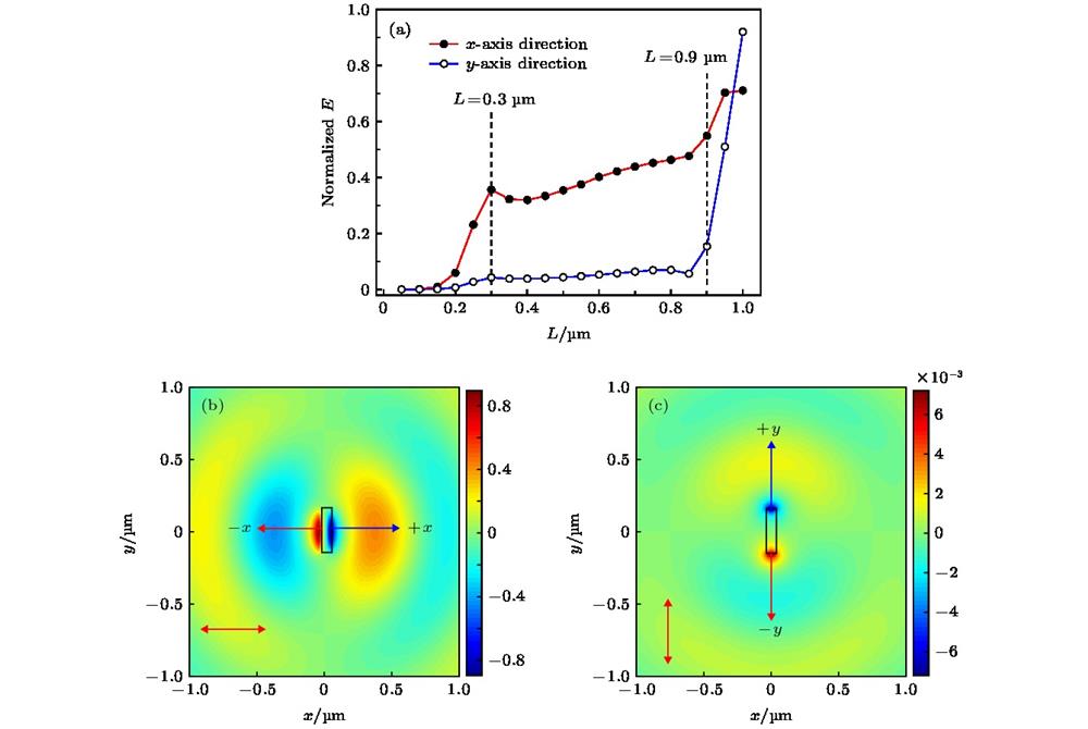
Fig. 1. SPPs field excited by rectangular nanoslit: (a) Electric field intensity along the L curves in the x and y direction with the x -direction linearly polarized light incident; (b) electric field excited by the incident light in the x direction; (c) electric field excited by the incident light in the y direction.
矩形纳米狭缝激发的SPPs场 (a) x 方向线偏振光入射下x 和y 方向电场强度随L 的变化; (b) x 方向线偏振光入射激发的场; (c) y 方向线偏振光入射激发的场
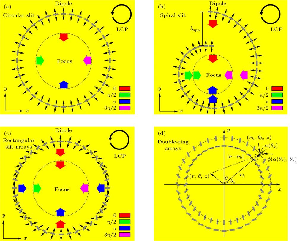
Fig. 2. Schematic diagram of excitation of SPPs by (a) circular slit, (b) spiral slit, (c) rotating rectangular nanoslit arrays under the incidence of left-handed circularly polarized light; (d) schematic diagram of double-ring rectangular nanoslit arrays.左旋圆偏振光入射下, (a) 圆狭缝、(b) 螺旋线狭缝、(c) 旋转排列的矩形纳米狭缝阵列激发SPPs原理示意图; (d) 矩形纳米狭缝双圆环阵列结构示意图
Fig. 3. Schematic diagram of compound focusing structure: (a) Two-dimensional top view; (b) sectional view.复合聚焦结构示意图 (a) 二维俯视图; (b) 截面侧视图
Fig. 4. Variation of the center electric field with the difference of slit depth.中心电场随狭缝深度差值变化趋势
Fig. 5. Simulation diagram of left-hand circularly polarized light incident structure: (a) Electric field distribution diagram; (b) cross-section curve of electric field intensity.左旋圆偏振光入射结构仿真图 (a) 电场分布图; (b) 电场强度切面曲线图
Fig. 6. Electric field distribution excited by linearly polarized light in different polarization directions: (a)
; (b)
; (c)
; (d)
.
不同偏振方向线偏振光激发的电场分布 (a)
; (b)
; (c)
; (d)
Fig. 7. Simulation curves of linearly polarized light incident structure: (a) Section curves of electric field intensity; (b) curve of the intensity of the central focal point changing with
.
线偏振光入射结构仿真曲线 (a) 电场强度切面曲线; (b) 中心聚焦点强度随
变化曲线
Fig. 8. Comparison of the excitation field intensity curves of the simple structure and the composite focusing structure.简单结构和复合聚焦结构激发场强度曲线对比

Set citation alerts for the article
Please enter your email address
© Copyright 2018-2021 | Chinese Laser Press. All Rights Reserved 沪ICP备15018463号-20