Xing Su, Longguang Xia, Kan Liu, Peng Zhang, Ping Li, Runchang Zhao, Bo Wang. Fabrication of a large-aperture continuous phase plate in two modes using atmospheric pressure plasma processing[J]. Chinese Optics Letters, 2018, 16(10): 102201
Copy Citation Text
In order to fabricate a large-aperture continuous phase plate (CPP) using atmospheric pressure plasma processing (APPP) with high efficiency and precision, the position dwell mode and velocity mode were proposed and the iterative calculation method was developed for the non-constant removal rate. Two 320 mm × 320 mm × 2 mm CPPs were fabricated with two processing modes. The experiment results show that the velocity mode is capable of significantly reducing the processing time and shape error. The total processing time is decreased from 13.2 h to 9.3 h, and the surface shape error is decreased from 0.158 to 0.119 ( = 632.8 nm) (root mean square).
Continuous phase plates (CPPs) are an important kind of diffractive optical element[1,2] that plays an important role in kilojoule- and megajoule-class laser systems of inertial confinement fusion projects such as the National Ignition Facility at Lawrence Livermore National Laboratory, Laser MegaJoule in France, and the SG-III laser facility in China[3–5]. The function of the CPP is to control the shape, wavefront profile, and energy distribution of the laser beam precisely through different continuously varying microstructures on its surface[6]. In recent years, atmospheric pressure plasma processing (APPP) has been proposed, which is a deterministic sub-aperture optical manufacturing technique with a stable and controllable Gaussian-shape influence function. These characteristics make it possible to fabricate a complex topographical CPP pattern with different spatial wavelengths and peak-to-valley (PV) values[7–10]. The position dwell mode in APPP, which refers to the plasma torch staying for the solved time at every dwell point along the given tool path to realize deterministic material removal, is generally applied to optical fabrication. However, there exist several obvious disadvantages in this mode. First, the movement between the neighboring dwell points generates extra processing time. Furthermore, the extra time increases linearly with the expansion of the machining region, especially for large-aperture CPP. Second, every dwell time is only a few seconds and the worktable starts and stops frequently, which seriously affects the processing stability.
In this Letter, the fabrication of CPP with two modes is studied. First, the principle of APPP is introduced. Then the position dwell mode and velocity mode are proposed. Considering the non-constant removal rate caused by the thermal effect, the iterative calculation method is developed. Finally, two CPPs are fabricated with the position dwell mode and velocity mode. The machining result with the velocity mode reduces the processing time and shape error, which demonstrates the industrial application of APPP for CPP and other free-form optics.
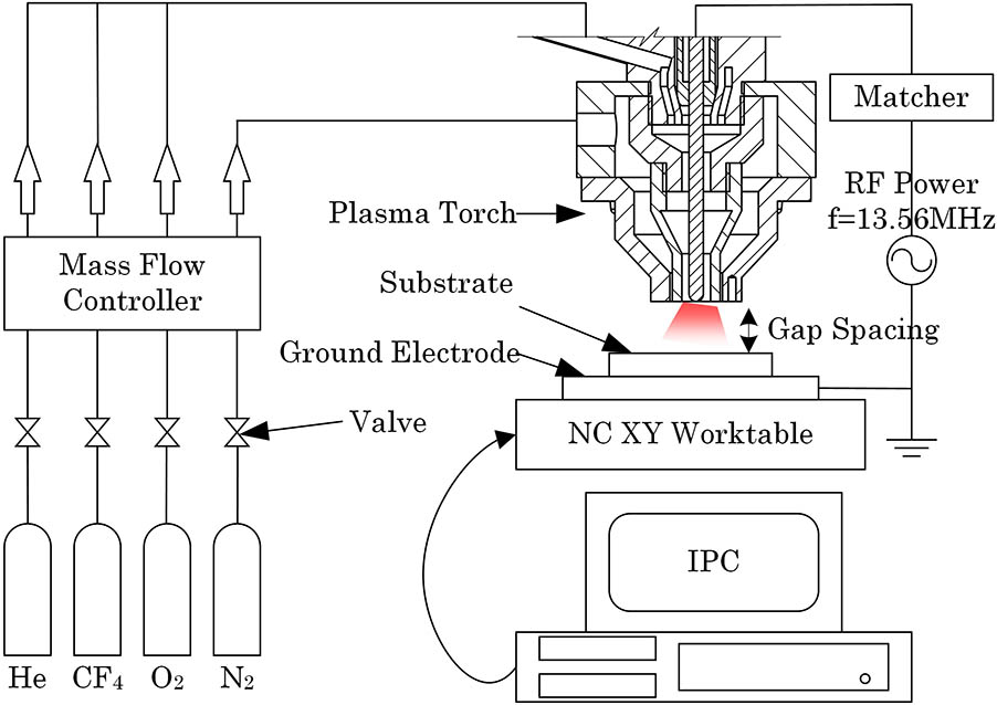
A schematic diagram of the APPP setup is shown in Fig. 1. The APPP setup is comprised of a plasma generation device, a gas supply system, and a computer numerical control (CNC) machine tool. In order to improve the stability of the plasma discharge, a double-inlet capacitive coupling plasma (CCP) torch with shielding gas was developed to avoid the surrounding flow disturbance. The inner mixed gas, including He, , and , is excited in a radio frequency (RF) electromagnetic field at the end of the needle electrode. The outer shield gas is . The flow rate of gas is managed precisely by the multi-channel mass flow controller.
Sign up for Chinese Optics Letters TOC. Get the latest issue of Chinese Optics Letters delivered right to you!Sign up now
Compared with traditional optical manufacturing techniques, the material removal mechanism of APPP is chemical etching at atmospheric pressure. The reactive fluorine species are generated by an RF electromagnetic field, and these species react with the substrate material. For a silicon-based material, the reaction product is gaseous at room temperature and the material removal is realized, as shown in Eq. (1).
The chemical etching process brings several advantages such as high efficiency, no sub surface damage, and low cost. Moreover, the influence function is a Gaussian shape that is suitable for fabricating free-form surfaces. Thus, APPP shows a strong potential to fabricate a large-aperture CPP.
A set of trench etching experiments were carried out to study the removal characteristics and to obtain the suitable parameters for fabricating CPP. Generally, the removal rate increases with the flow rate of and reaches a saturation point. By the addition of , the removal rate increases while the discharge process becomes slightly unstable at 20 sccm (standard cubic centimeter per minute). Figure 2 shows that the peak removal rate and full width at half-maximum (FWHM) are sensitive to the flow rate of He because the concentration of reactive species decreases, and the total gas flow increases with the increase of the He flow rate. It is worth mentioning that the black line only represents the trend of the volume removal rate in Fig. 2, and the volume removal rate reaches a maximum when the flow rate of He is 1700 sccm under our experimental conditions. According to RF power fluctuation at different feed velocity, the minimum flow rate of was obtained as 2000 sccm, which can avoid influence from the surrounding flow disturbance. Considering the removal rate and discharge stability, the processing parameters were chosen as follows: the flow rates of He, , , and N2 are 1700, 120, 20, and 2000 sccm, respectively; the gas pressure is 0.25 MPa; the gap spacing between electrodes is 2 mm; the RF power is 100 W.
Figure 2.Effects of the He flow rate on the influence function.
APPP is a typical sub-aperture optical fabrication method that belongs to computer-controlled optical surfacing (CCOS). The total material removal distribution is determined by two-dimensional convolution between the unit influence function and the dwell time or velocity in CCOS[11,12]. Compared with other solution algorithms, the linear equations method is simple and highly efficient, with enough accuracy[13–16]. In this method, the total amount of material removal can be expressed as
In Eq. (2), the -dimensional column vector is called the ideal removal amount of the designed surface shape. The ideal removal distribution is divided into discrete points based on the processing step. is called the proportional factor, which equals the reciprocal of the velocity or dwell time. is called the influence function matrix, which is generated by the unit time influence function or the unit velocity influence function, depending on the processing mode. The element in matrix denotes the unit removal amount at point , when the plasma torch dwells at point or feeds at segment .
Given a desired surface shape, there are two machining modes, which are the position dwell mode and velocity mode. The unit influence function in the position dwell mode refers to the fact that the plasma torch rests for unit time at one dwell point. The profile of the influence function is approximately an ideal Gaussian-shape, as shown in Fig. 3. The function expression is shown in Eq. (3):
Figure 3.Profile of the influence function in the position dwell mode: (a) a three-dimensional graph, (b) the cross-section plot.
The variable is the peak removal rate and is the standard deviation. The unit influence function in the velocity mode is derived from the one in the position dwell mode. It is defined as the unit time that the influence function moves a step at unit speed. The function expression is shown in Eq. (4):
The variable is the processing step and is the error function. The profile of influence function is a stretched Gaussian-shape, as shown in Fig. 4.
Figure 4.Profile of the influence function in the velocity mode.
The linear equations in Eqs. (2) can be solved using the multi-objective optimization method. The mathematical model can be described as where is the 2-norm of the residual error, constant vectors and are the lower and upper limit of velocity, is the first-order difference function, and is the upper limit of acceleration. In position dwell mode, due to the start-stop motion, there is no limitation for the dwell time and the is set as zero. On the other hand, the dynamic performance of the machine tool needs to be considered in the velocity mode. In this study, the limitations are set as , , and .
Since the APPP is a chemical etching method and the chemical reaction is influenced by temperature, the removal rate changes with the dwell time or velocity, which introduces a non-linear influence on the machining process. Figure 5 shows how the peak removal rate changes with velocity. Note that the FWHM changes a little within 6% and is considered as a constant in this Letter.
In the linear equations method for the dwell time or velocity, the removal rate is supposed to be constant. The changing peak removal rate makes it difficult to obtain the constant unit influence function shown in Eq. (2). Therefore, an iterative calculation method was developed for calculating the dwell time or velocity properly. At first, an expected dwell time or velocity is estimated and the peak removal rate can be determined based on the fitting curve in Fig. 5. Then, the dwell time or velocity is calculated using the linear equations method. For convenience of analysis, the dwell time is transformed into velocity and the accumulative probability of the velocity is obtained, as shown in Fig. 6. Based on machining experience, the estimated velocity should locate at a cumulative probability, where the machining error is minimized. The estimated velocity needs to be adjusted and the velocity is calculated again, until it reaches the cumulative probability, which can be called the optimal calculation condition.
Figure 6.Schematic of the optimal calculation condition.
Verification tests were carried out to fabricate two CPPs with these two processing modes. The designed surface shape of the CPP is shown in Fig. 7. The material of the substrate is floated borosilicate glass produced by Schott corporation. The PV value is 4.44 (), and the spatial wavelength distribution is about 10–30 mm. The dwell time and velocity were calculated using the iterative calculation method. The spacing of discrete points in the calculation is 1 mm and the designed surface is divided into discrete points.
To compare these two machining modes, the total dwell time in the position dwell time mode was transformed into velocity. Figure 8 shows the velocity distribution and cumulative probability of these two modes. In the velocity mode, the velocity of 90% of the machining points ranges from 1.7 to 5.1 mm/s, and the related peak removal rate changes from 16.1 to 15.3 μm/min. In the position dwell mode, the velocity of 90% of the machining points ranges from 1.2 to 2.5 mm/s, and the related peak removal rate changes from 16.4 to 15.7 μm/min. The changes in the peak removal rate in the two machining modes are almost equal, but the change rate of the peak removal rate in the position dwell mode is much larger than that in the velocity mode, shown in Fig. 5, which means that the fluctuation of the feed velocity in practice introduces more machining error in the position dwell mode. In addition, the total material removal in the position dwell mode is larger than that in the velocity mode, and thus the machining error will be enlarged. In the position dwell mode, the actual machining process includes the start-stop motion and point dwell, so the extra processing time is introduced. Therefore, the velocity mode shows advantages in efficiency and machining accuracy.
Figure 8.Cumulative probability of velocity: (a) the velocity mode, (b) the position dwell mode.
The schematic diagram of fabricating a CPP is shown in Fig. 9. The photograph of the APPP setup during processing a CPP is shown in Fig. 10. The substrate was placed on the plate ground electrode fixed on the worktable. The plasma torch was stationary at the axis of the 5-axis CNC machine tool. During the manufacturing process, the worktable movement was controlled by NC codes generated by the calculation results along a raster tool path. In order to shield electromagnetic radiation, the machining tool was wrapped by iron gauze.
Figure 9.Schematic diagram of fabricating the CPP.
The machining results with the position dwell mode and the velocity mode are shown in Figs. 11 and 12, measured by an interferometer (MST Verifire, Zygo). The overall topographical pattern is very similar to the designed surface shape of the CPP. The total processing time of the position dwell mode and velocity mode is 13.2 h and 9.3 h, respectively. The shape errors of the position dwell mode and the velocity mode are 0.158 and 0.119 (root mean square, RMS), respectively.
Figure 11.Actual surface shape with the position dwell mode.
In conclusion, APPP is a deterministic sub-aperture optical manufacturing technique with a Gaussian-shaped influence function that is suitable for fabricating complex free-form optics such as a large-aperture CPP. To fabricate CPP, the position dwell mode and velocity mode were proposed. Considering the non-constant removal rate of APPP, the iterative calculation method was proposed to calculate the dwell time or velocity. Two CPPs were fabricated using these two processing modes. The total processing time and surface shape error of the velocity mode are 9.3 h and 0.119 RMS, both of which are smaller than those of the position mode. Moreover, the processing efficiency increased by 30%. The results indicate that APPP has a strong ability to fabricate CPPs and the velocity mode can reduce the processing time and shape error.
Xing Su, Longguang Xia, Kan Liu, Peng Zhang, Ping Li, Runchang Zhao, Bo Wang. Fabrication of a large-aperture continuous phase plate in two modes using atmospheric pressure plasma processing[J]. Chinese Optics Letters, 2018, 16(10): 102201