Key Laboratory of OptoElectronic Science and Technology for Medicine of Ministry of Education, Fujian Provincial Key Laboratory for Photonics Technology, Institute of Laser and Optoelectronics Technology, Fujian Normal University, Fuzhou 350007, China
Definitions of mode-field half-width and divergence half-angle according to different kinds of methods are analyzed in this work. Numerical results of these definitions are given for the fundamental mode and suggest that some of them are more suitable for describing the transmission characteristics of a slab waveguide.
Since the advent of optical waveguides, guided-wave optics technology has been the focus of optics communication[1–5]. It has developed quickly and gives powerful impetus to technology innovation in our modern life and has become the focus of the information industry[6–8]. Its propagation characteristics, such as the near-field and far-field characteristics, are often depicted by the mode-field half-width and divergence half-angle, respectively, and a problem is how to exactly to determine them.
As one of the most important parameters for slab waveguides, mode-field half-width relates to various transmission characteristics and attracts more attention[9,10]. According to ISO 11146-1: 2005[11], a combination of mode-field half-width, divergence half-angle, and beam propagation factor produces a general method to evaluate practical beam quality. Therefore, the divergence half-angle of the far-field should be of concern as well.
There are two kinds of definitions of mode-field half-width for slab waveguides based on the second-moment and differential operator[12,13], and then there are the second-moment and differential operator divergence half-angle according to the two kinds of definitions. Researchers have also presented a definition for the two parameters[14]. However, they are different from each other.
Sign up for Chinese Optics Letters TOC. Get the latest issue of Chinese Optics Letters delivered right to you!Sign up now
In this work, definitions for mode-field half-width and divergence half-angle referring to different kinds of methods were researched. Then, numerical results of these mode-field half-width and divergence half-angle of the mode in step-index slab waveguides are given and numerical calculation proves that some of them are more suited than others to describe the near-field and far-field based on their respective power in the bucket. These conclusions may provide a theoretical foundation for analyzing the propagation characteristics of optical waveguides.
In the space domain, there are many kinds of traditional definitions of laser beam spot size for illuminating the propagation characteristics of laser beams; thus, we try to define mode-field half-width of a slab waveguide in view of these definitions and discuss their properties. The entropy-based mode-field half-width is presented according to the Shannon’s information-entropy formula[15]where is the near-field distribution.
The mode-field half-width is defined in terms of the light of the power in the bucket where , and is given as where and the subscript max refers to the maximum.
For slab waveguides, Liang and Hayata presented two definitions based on the second-order-moment and differential operator , respectively[12,13]
Researchers have also introduced a definition for mode-field half-width [14]where the subscript denotes the relationship to the definitions of mode-field half-width.
The near-field characteristic of the mode in a step-index slab waveguide is presented as an example to find whether these definitions are suitable for slab waveguides. From the analytical field solution of the mode where β and β are the normalized standing wave parameter and the normalized evanescent wave parameter, respectively; the normalized frequency ; is the half thickness of the core layer; is the wave number in vacuum; β is the propagation constant; is the wavelength of the electromagnetic wave in vacuum; and are the refractive indices of the core layer and cladding layer, respectively. We can obtain the mode-field half-width and make various comparisons.
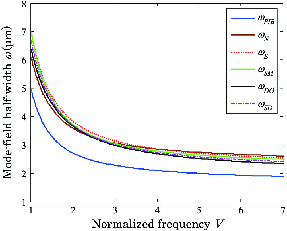
Numerical results of mode-field half-width based on different definitions are displayed in Fig. 1. Figure 1 shows that with the increase of normalized frequency, all the mode-field half-width decreases and the difference among them is large when the normalized frequency is small. We can also see that is smaller than the other kinds of mode-field half-width.
Figure 1.Mode-field half-width versus normalized frequency, where μ and μ.
Furthermore, the power in the bucket as function of mode-field half-width versus normalized frequency is shown in Fig. 2. It is obvious that all kinds of mode-field half-widths can exactly reflect the energy concentration except for power in the bucket-based mode-field half-width , and most of beam energy is occupied in the range of mode-field half-width. If as an example, the power in the bucket is , , , , , and . Thus, we can draw a conclusion that similarly to the mode-field half-widths of a slab waveguide , and , and can be a good choice for description of the near-field characteristic.
Figure 2.Power in the bucket as function of mode-field half-width versus normalized frequency.
The far-field characteristic of a slab waveguide is described by the divergence half-angle and we can introduce their definitions according to the mode-field half-width definitions. The entropic divergence half-angle is defined as where is the spatial frequency spectrum, is the inclination angle, and and are given in the following Accordingly, the second-order moment as well as differential operator divergence half-angle are introduced and the new definition is
For the mode, the spatial frequency spectrum of the far-field is given as[16]where is the spatial frequency.
Combining Eqs. (9)–(14) with Eq. (15), relational curve between divergence half-angle and normalized frequency is shown in Fig. 3. It is obvious that the divergence half-angle increases with increasing normalized frequency and deviation also becomes large. Similarly to the mode-field half-width, is the smallest compared to other kinds of divergence half-angles.
Figure 3.Divergence half-angle versus normalized frequency.
More specifically, the power in the bucket based on all other kinds of divergence half-angles is far greater than displayed in Fig. 4. For example, , , , , , and when according to the aforementioned parameters. Consequently, and can be used for describing the far-field characteristic compared to the divergence half-angle of slab waveguides , , and .
Figure 4.Power in the bucket as function of divergence half-angle versus normalized frequency.
In conclusion, mode-field half-widths and divergence half-angles based on different kinds of definitions are investigated. Numerical calculation proves that , , , , as well as are fit to depict the near-field of slab waveguides, and , , , , as well as are suitable for illuminating the characteristic of the far-field. These conclusions may provide theoretical groundwork for further researching beam propagation characteristics of slab waveguide.