
Yuancheng Cai, Xiang Gao, Yun Ling, Bo Xu, Kun Qiu. Power-efficient heterodyne radio over fiber link with laser phase noise robustness[J]. Chinese Optics Letters, 2019, 17(11): 110602
- Chinese Optics Letters
- Vol. 17, Issue 11, 110602 (2019)
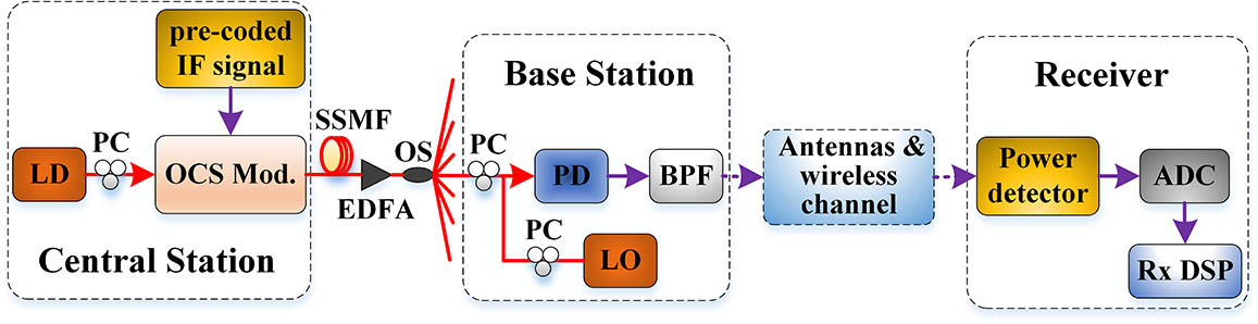
Fig. 1. Schematic architecture of the proposed RoF link based on pre-coding-assisted power detection scheme. LD, laser diode; PC, polarization controller; OCS, optical carrier suppression; Mod, modulation; SSMF, standard single mode fiber; OS, optical splitter; LO, local oscillator; PD, photodetector; BPF, bandpass filter; ADC, analog-digital converter; DSP, digital signal processing. The later experimental setup has been simplified by omitting the wireless transmission link, whilst the BPF and power detection are conducted in digital domain.
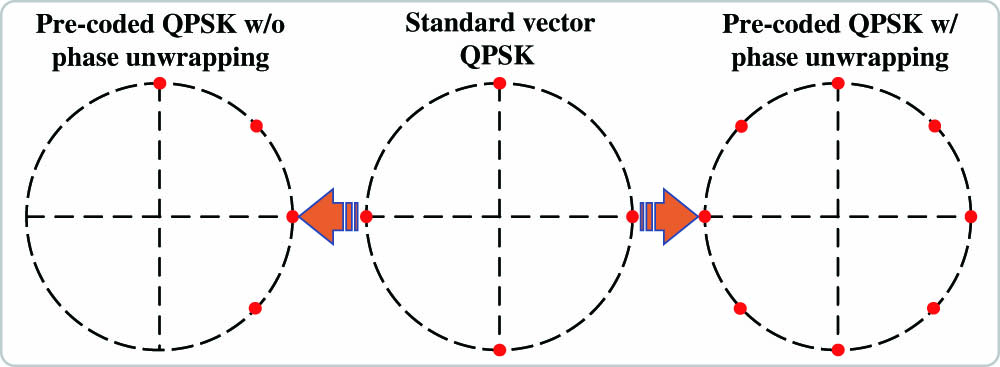
Fig. 2. Principle diagram of the pre-coded QPSK signal with and without phase unwrapping.
Fig. 3. Spectra of transmitted pre-coded QPSK IF signal with and without phase unwrapping in the signal pre-coding after pulse-shaping case.
Fig. 4. SNR vs RRC roll-off factor curves for QPSK with and without phase unwrapping using different sequence of pulse shaping and pre-coding. PCAPS, signal pre-coding after pulse shaping; PCBPS, signal pre-coding before pulse shaping.
Fig. 5. Spectrum of received QPSK signal with phase unwrapping at the ROP of −2 dBm after the PD. Symbol rate: 625 MSymbol/s; IF center frequency: 0.625 GHz; RF center frequency: 7.5 GHz.
Fig. 6. BER vs ROP curves for 1.25 Gbps QPSK, and 2.5 Gbps square and star 16-QAM signals transmitted over 75 km fiber in the case of two LO lasers with different linewidths. Insets depict the constellation diagrams of (i) QPSK, (ii) square 16-QAM, and (iii) star 16-QAM at the ROP of −25 dBm, respectively.
Fig. 7. BER vs ROP performance comparison for QPSK signal between the proposed pre-coding-assisted power detection scheme and conventional power detection scheme after 75 km fiber transmission. Insets (i) and (ii) depict the constellation diagrams of the two schemes at the fixed ROP of −38 dBm, respectively.

Set citation alerts for the article
Please enter your email address
© Copyright 2018-2021 | Chinese Laser Press. All Rights Reserved 沪ICP备15018463号-20