Abstract
In this work, we propose a new scheme to generate frequency-doubled vortex beams from a radially poled LiNbO3 micro-ring resonator based on nonlinear Cherenkov radiation. The near-infrared fundamental wave is resonant in the micro-ring, while the second harmonic is emitted from the resonator along the Cherenkov phase-matching direction. The topological charge of the emitted second-harmonic vortex beam is determined by both the azimuthal order of the whispering galley modes and the number of nonlinear grating elements. The field distribution and the conversion efficiency of the emitted vortex beam are investigated.Light beams with helical phase fronts are called vortex beams, and they carry an orbital angular momentum (OAM) of per photon[1]. Due to the unique properties of such beams, increasing attention has been paid in the area of modern optics and photonics in recent years. For example, the hollow intensity distribution of vortex beams provides a gradient force that can be used for optical manipulation[2], trapping[3], tweezers[4], as well as super-resolution microscopy[5]. Moreover, the OAM has infinite orthogonal states, and this property makes OAM beams suitable for high-capacity optical communications[6–8] and quantum teleportation systems[9].
There are a variety of methods for generating vortex beams[10], and most of them are based on bulk optical elements such as mode converters using cylindrical lenses[11], spiral phase plates (SPPs)[12], spatial light modulators based on computer-generated holograms[13], q-plates[14], nano-antenna arrays[15], and OAM states from laser cavities[16–18]. In comparison with bulk optical components, integrated vortex beam generators based on planar waveguides[19,20] have advantages in reliability, miniaturization, and scalability. The working principle in the representative work[20] is that angular gratings are introduced into silicon micro-ring resonators to extract the whispering galley modes (WGMs), which carry a high OAM[21], into free space. This is a linear optical process, and the topological charge of the emitted vortex beam is determined by the azimuthal order of the WGMs involved and the number of grating elements. In this work, we propose a new scheme for emitting the WGMs of a radially poled micro-ring resonator into free space exploiting the nonlinear Cherenkov radiation effect[22–24]. The angular frequency of the emitted vortex beams is twice the resonant frequency of the micro-ring resonator, and the topological charge (TC) of the generated vortex beams is determined by both the azimuthal order of the WGMs involved and the poling period of the ferroelectric domain structure.
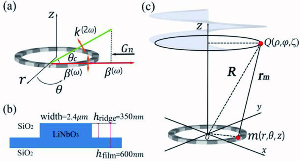
Nonlinear Cherenkov radiation (NCR) is the optical analog to the conventional Cherenkov radiation in particle physics. When the phase velocity of the nonlinear polarization wave (NPW) in the nonlinear medium is larger than that of the harmonic wave , then a coherent harmonic wave would be emitted along the Cherenkov angle . In nonlinear waveguides with ferroelectric domain structures, such as periodically poled waveguides, nonlinear Cherenkov radiation can be modulated by the reciprocal vectors provided by the structure. Let us take Cherenkov-type second harmonic generation (SHG) as an example, and the phase-matching condition shown in Fig. 1(a) is given by where is the propagation constants of the guided mode in the micro-ring resonator. and are wave vectors of the second harmonic (SH) in the substrate and waveguide, respectively, and the corresponding radiation angles are and , respectively. is the -order reciprocal vector, with being the poling period. The phase velocity of the NPW is decreased by the forward reciprocal vectors, while it is increased by the backward reciprocal vector. In the latter case, the Cherenkov radiation angle will become larger. For Cherenkov radiation in nonlinear waveguides, it is a guided-to-radiation nonlinear process[25–27], which means the fundamental wave (FW) is in the guided mode while the harmonic wave is radiated into the substrate. When the Cherenkov-type phase-matching diagram is applied to micro-ring resonators, vortex beams with doubled frequency may be emitted along the Cherenkov angle.
Sign up for Chinese Optics Letters TOC. Get the latest issue of Chinese Optics Letters delivered right to you!Sign up now

Figure 1.(a) Schematic of the phase-matching diagram for emitting vortex beams with doubled frequency; the orange arrow represents the polarization direction of the FW and the SH wave. (b) Cross section of the micro-ring resonator. (c) Illustration of the polar coordinate system and the emitted SH vortex beam with a helical phase front.
We choose a micro-ring resonator as the material platform to investigate the proposed scheme, as shown in Fig. 1(b). The micro-ring resonator is formed on a Z-cut thin film, and it is surrounded by . The electric field of the FW in the resonator can be described as , where is the amplitude, is the effective radius of the micro-ring, and is the normalized transverse mode profile. The is the azimuthal order, which corresponds to the topological charge of the FW in the resonator. To emit the SH wave into the substrate, a radially poled ferroelectric domain structure is introduced to form a nonlinear angular grating. The second-order nonlinear susceptibility , which varies with the azimuthal angle, can be expanded into the Fourier series, and thus the NPW is written as where is the number of periodically inverted domain structures with 50% duty cycle, is an element of the second-order susceptibility tensor of , and is the dielectric constant in vacuum. From Eq. (2), one can see that the NPW consists of different OAM modes, which could be coherently emitted into the substrate as long as the phase-matching condition is fulfilled. Referring back to Eq. (1), the Cherenkov-type phase-matching condition in the resonator can be expressed in the form of where is the azimuthal propagation constant of the radiation mode, which corresponds to the TC of the emitted SH vortex beam. The above analysis shows that the TC of the emitted vortex beam from the resonator is determined by both the azimuthal order of the WGMs and the radially poled ferroelectric domain structure.
To analyze the electric field of the radiated wave, we establish the polar coordinate system based on the center of the micro-ring, with being the distance from the observation plane to the plane of the micro-ring as shown in Fig. 1(c). The radiated SH wave is excited by the dipoles on the nonlinear micro-ring resonator which can be expressed as [28], with being the vector pointing from to . The SH field is the interference of the radiation field excited by the numerous points on the micro-ring resonator, which can be expressed as the spatial integration: where is the speed of light in vacuum and is the vector pointing from to . Eq. (4) provides the full information of the SH field, including the amplitude, the phase, and the polarization. For the numerical simulations, the radius , the width and the height of the ridge, and the total thickness of the thin film are chosen to be 80 μm, 2.4 μm, 350 nm, and 600 nm, respectively. The resonance wavelength of the micro-ring is set to be 1064 nm and the temperature is set to be 25°C, and thus the azimuthal order can be calculated to be 990. The normalized mode profile is simulated using COMSOL Multiphysics. It is worth noting that, to avoid total reflection when the emitted OAM beam strikes the -air interface, our simulation begins with .
The micro-ring resonator supports both quasi-TE and quasi-TM polarization modes. During the study, we found that distribution of the NPW as well as the effective second-order nonlinear coefficient are quite complicated when the FW is in the TE mode. In this work, we only consider the situation when the TM mode is excited in the micro-ring resonator. In this case, the induced second-order nonlinear polarization only contains the component or component in the direction, which can be written as[29]where is the largest second-order nonlinear coefficient of . As the first-order backward reciprocal vector is utilized, we only consider the Fourier component in Eq. (2) with , and thus the TC of the emitted optical vortex beam is . From Eq. (5), one can see that the polarization direction of the NPW is the same as that of the TM polarized FW along the axis. We consider the situation in which the observing point is far from the dipoles of the waveguide, taking the approximate solution with the relation . Equation (4) can be expressed in the form of radial, azimuthal, and vertical field components, with
Based on Eq. (6), the far field of the NCR from the ring-resonator can be calculated. As shown in Fig. 2(a), the beam profile contains multiple concentric rings, and the intensities attenuate as the radius increases. The phase distribution in Fig. 2(b) shows an angular dependence of , indicating the existence of OAM.
Figure 2.Simulated (a) intensity distribution and (b) phase of the emitted SH wave excited by TM polarized FW. The TC of the SH vortex beam is .
The normalized intensity of the radial, azimuthal, and vertical components of the SH wave are shown in Figs. 3(a)–3(c), respectively. We can see that the major components are and , which have similar profiles to the total field distribution as shown in Fig. 2(a). The intensity of the longitudinal component is much less than that of the transverse component due to the large radiation angle, which is about 88.2°.
Figure 3.Simulated intensity distributions of different components (a) , (b) , and (c) , with .
In addition to the field distribution of the generated SH vortex beam, we investigate the conversion efficiency for the frequency-doubled vortex beam emitter based on NCR. The energy stored in the micro-ring cavity can be evaluated from the definition of the -factor, [30], in which is the resonant frequency and is the lost power. Considering the low conversion efficiency of Cherenkov-type SHG, the depletion of the FW is neglected, and thus is approximately equal to the power coupled into the ring resonator . The amplitude of the FW can be written as
Substituting the field amplitude of the FW into Eq. (6), we can obtain the electric field intensity of the SH wave. Subsequently, by integrating the Poynting vector, the power of the emitted SH can be described as[31]
The -factor of the micro-ring resonator is set to be , and the power coupled into the resonator is assumed to be 10 mW. The conversion efficiency varying with the poling periods is listed in Table 1. When the poling periods become smaller, which corresponds to the increase of the reciprocal vector, the emitting angle will increase while the TC of the emitting vortex beams will decrease. As we know, Cherenkov-type phase-matching is a partially phase-matched diagram in which the transverse direction is phase matched while there is a phase mismatch in the longitudinal direction ( direction). As the FW in the resonator is highly confined in the direction, the wave vector mismatch can be partly compensated by the momentum fluctuation. The phase mismatch in the direction will increase with the Cherenkov angle, and thus the conversion efficiency decreases dramatically when the poling periods become smaller. Another factor that will affect the conversion efficiency is the effective nonlinear coefficient. The effective nonlinear coefficient can be expressed as , thus the increase of the Cherenkov angle will lower the effective nonlinear coefficient, and the conversion efficiency will decrease accordingly.
| Poling Period (nm) | 500 | 390 | 330 |
|---|
| Radiation angle (θc) | 45° | 60° | 70° |
| Topological charge (l) | 976 | 674 | 444 |
| Conversion efficiency | 4.11×10⁻⁴ | 1.68×10⁻⁴ | 2.02×10⁻⁵ |
Table 1. Cherenkov Radiation Angle, Topological Charge, and Conversion Efficiency Varying with the Poling Period
When the working temperature changes, the propagation constant of the FW will change accordingly. To ensure the azimuthal order of the resonant FW, which is determined by to be an integer, the temperature can only take discrete values. The azimuthal order of the FW will be increased by 1 when the temperature reaches 89°C, and the corresponding topological charge of the SH is increased from 976 to 978, the poling period being 500 nm. In addition, the radiation angle and the conversion efficiency will be changed to 44.9° and , respectively. Besides the platform used in the simulation, MgO-doped (MgO:LN) can be also used. The second-order nonlinear coefficients of and MgO:LN are almost the same[32]. However, the dispersion relation of the two crystals is different[33], and there is a slight refractive index difference between them. When the materials platform is changed to MgO:LN, SH vortex beams will still be emitted out because the Cherenkov phase-matching condition can be satisfied by automatically changing the radiation angle. For a fixed poling period of 500 nm, the radiation angle is changed from 45.0° to 45.6°, the topological charge of the SH vortex beam is changed from 976 to 964, and the conversion efficiency is slightly changed from to .
To conclude, we have proposed, in theory, a novel scheme to generate frequency-doubled vortex beams from micro-ring resonators. The material used in the theoretical model is a radially polled micro-ring resonator and the phase-matching diagram of the SHG process is of the nonlinear Cherenkov-type configuration. By analyzing the nonlinear polarization wave in the micro-ring resonator, we can determine the TC of the emitted SH vortex beam, which is the difference between twice the TC carried by the FW and the number of periodically inverted domain structures. The intensity and phase distributions of the emitted vortex beam are simulated by considering the dipoles around the micron-ring, and the emitted SH wave from the dipoles is a coherent superposition determined by the Cherenkov-type phase-matching diagram. In addition, we estimate the conversion efficiencies with different poling periods, which are mainly determined by the radiation angle related phase mismatch in the longitudinal direction and the effective nonlinear coefficient. The work presented in this Letter is a theoretical work. Regarding the recent developments in the fabrication of micro-ring resonators with a high quality factor up to [34], as well as the realization of a ferroelectric domain structure with a period being hundreds of nanometers in MgO:LN[35], it is possible to verify the proposed scheme in experiments. The vortex emitter based on nonlinear frequency conversion can not only work at the new wavelength, but also manipulate the topological charge of the emitted vortex beam by design of the ferroelectric domain structure. Further work can be extended to other nonlinear integrated photonic devices, such as terahertz vortex emitters based on difference frequency generation, and wavelength tunable vortex beam emitters exploiting frequency down conversions.
References
[1] L. Allen, M. W. Beijersbergen, R. J. C. Spreeuw, J. P. Woerdman. Phys. Rev. A, 45, 8185(1992).
[2] D. G. Grier. Nature, 424, 810(2003).
[3] L. Paterson, M. P. MacDonald, J. Arlt, W. Sibbett, P. Bryant, K. Dholakia. Science, 292, 912(2001).
[4] A. Ashkin. Phys. Rev. Lett., 24, 156(1970).
[5] S. Fürhapter, A. Jesacher, S. Bernet, M. Ritsch-Marte. Opt. Express, 13, 689(2005).
[6] J. Wang, J.-Y. Yang, I. M. Fazal, N. Ahmed, Y. Yan, H. Huang, Y. Ren, Y. Yue, S. Dolinar, M. Tur, A. L. Willner. Nat. Photonics, 6, 488(2012).
[7] N. Bozinovic, Y. Yue, Y. Ren, M. Tur, P. Kristensen, H. Huang, A. E. Willner, S. Ramachandran. Science, 340, 1545(2013).
[8] S. Fu, Y. Zhai, H. Zhou, J. Zhang, C. Yin, C. Gao. Chin. Opt. Lett., 17, 080602(2019).
[9] M. Mirhosseini, O. S. Magaña-Loaiza, M. N. O’Sullivan, B. Rodenburg, M. Malik, M. P. Lavery, M. J. Padgett, D. J. Gauthier, R. W. Boyd. New J. Phys., 17, 033033(2015).
[10] J. Wang. Chin. Opt. Lett., 16, 050006(2018).
[11] M. W. Beijersbergen, L. Allen, H. Van der Veen, J. Woerdman. Opt. Commun., 96, 123(1993).
[12] M. Beijersbergen, R. Coerwinkel, M. Kristensen, J. Woerdman. Opt. Commun., 112, 321(1994).
[13] N. Heckenberg, R. McDuff, C. Smith, A. White. Opt. Lett., 17, 221(1992).
[14] L. Marrucci, E. Karimi, S. Slussarenko, B. Piccirillo, E. Santamato, E. Nagali, F. Sciarrino. J. Opt., 13, 064001(2011).
[15] N. Yu, P. Genevet, M. A. Kats, F. Aieta, J.-P. Tetienne, F. Capasso, Z. Gaburro. Science, 334, 333(2011).
[16] D. Naidoo, F. S. Roux, A. Dudley, I. Litvin, B. Piccirillo, L. Marrucci, A. Forbes. Nat. Photonics, 10, 327(2016).
[17] D. Wei, Y. Cheng, R. Ni, Y. Zhang, X. Hu, S. Zhu, M. Xiao. Phys. Rev. Appl., 11, 014038(2019).
[18] Q. Zhang, J. Yu, B. Shi, F. Tang, J. Li. Chin. Opt. Lett., 17, 051402(2019).
[19] P. Miao, Z. Zhang, J. Sun, W. Walasik, S. Longhi, N. M. Litchinitser, L. Feng. Science, 353, 464(2016).
[20] X. Cai, J. Wang, M. J. Strain, B. Johnson-Morris, J. Zhu, M. Sorel, J. L. O’Brien, M. G. Thompson, S. Yu. Science, 338, 363(2012).
[21] A. B. Matsko, A. A. Savchenkov, D. Strekalov, L. Maleki. Phys. Rev. Lett., 95, 143904(2005).
[22] H. Ren, X. Deng, Y. Zheng, N. An, X. Chen. Phys. Rev. Lett., 108, 223901(2012).
[23] Y. Zhang, Z. D. Gao, Z. Qi, S. N. Zhu, N. B. Ming. Phys. Rev. Lett., 100, 163904(2008).
[24] X. Chen, K. Switkowski, X. Hu, W. Krolikowski, Y. Sheng. Opt. Express, 24, 29948(2016).
[25] Y. Chen, Z. Ye, Y. Wu, Y. Niu, R. Ni, X. Hu, Y. Zhang, S. Zhu. Opt. Express, 26, 2006(2018).
[26] C. Chen, J. Lu, Y. Liu, X. Hu, L. Zhao, Y. Zhang, G. Zhao, Y. Yuan, S. Zhu. Opt. Lett., 36, 1227(2011).
[27] V. Roppo, K. Kalinowski, Y. Sheng, W. Krolikowski, C. Cojocaru, J. Trull. Opt. Express, 21, 25715(2013).
[28] C. Yao, F. J. Rodriguez, J. Bravo-Abad, J. Martorell. Phys. Rev. A, 87, 063804(2013).
[29] A. Yariv. Quantum Electronics(1975).
[30] U. A. Bakshi, A. V. Bakshi. Network Analysis(2009).
[31] G.-D. Xu, Y.-H. Wang, Y.-Y. Zhu, S.-N. Zhu, N.-B. Ming. J. Opt. Soc. Am. B, 21, 568(2004).
[32] K. Sakai, Y. Koyata, S. Itakura, Y. Hirano. J. Lightwave Technol., 27, 590(2009).
[33] O. Gayer, Z. Sacks, E. Galun, A. Arie. Appl. Phys. B, 91, 343(2008).
[34] M. Zhang, C. Wang, R. Cheng, A. Shams-Ansari, M. Lončar. Optica, 4, 1536(2017).
[35] Y. Dong, Q. Dong. Mater. Res. Express, 5, 035004(2018).