
Berta García-Fernández, Daniel Vázquez-Moliní, Antonio Álvarez Fernández-Balbuena, Angel García-Botella, Juan Carlos Martínez Antón, "Light losses in hollow, prismatic light guides related to prism defects: a transmittance model," Chin. Opt. Lett. 13, 092201 (2015)
- Chinese Optics Letters
- Vol. 13, Issue 9, 092201 (2015)
Abstract
The use of natural light inside buildings provides high-quality lighting, reduces energy consumption, and increases comfort and productivity. Light pipes can transfer light from a building’s roof into the depths of the building. The overall wattage of the installed lights is reduced, and therefore, the consumption of electricity decreases, due to the decreased use of artificial lighting. Tubular light guides are a complementary product to conventional skylights and windows that can complement the artificial lighting in areas not usually covered by windows and skylights[
Prismatic light guides are hollow structures internally covered with prismatic sheet; they offer a technical alternative for light transport in tubular guidance systems. The prismatic light guide leads light beams using total internal reflection (TIR) and provides light transmission with high efficiency and homogeneous light distribution in buildings with minimal color shifts[
Whitehead[
Sign up for Chinese Optics Letters TOC. Get the latest issue of Chinese Optics Letters delivered right to you!Sign up now
In this Letter, we study the effects of prism corner geometries and imperfections on the efficiency of light guides. For this purpose, scanning electron microscopy (SEM) and the topographic optical profilometry by absorption in fluids (TOPAF) imaging technique[
Surface roughness and irregularities are important factors in determining the satisfactory performance of the prismatic film structure. In order to quantify the area of the irregularities, the surface measurement that takes the nanometric scale into account has been quantified by two systems: SEM and the TOPAF imaging technique.
SEM (Jeol, JSM-6400) was used in order to determine the surface topography measurements and the quality of the corners. Prior to imaging, samples were mounted onto the sample holder and sputter coated with a thin gold layer (8 nm). They were then studied with SEM using an acceleration potential of 25 kV.
Figure
![]()
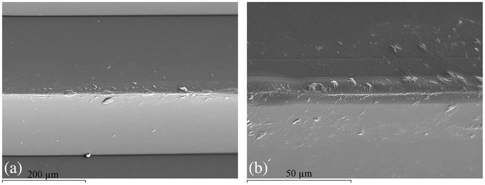
Figure 1.Top view of prismatic film. (a) SEM surface image of polycarbonate thin prismatic film surface sputter coated with a thin gold layer. (b) A detail of the vertex.
The results obtained with this technique provide only an approximation of measures because SEM is basically a two-dimensional technique. Three-dimensional (3D) information could only be obtained by tilting the sample. Thus, to determine this change in the corners of the prisms, the defects are investigated by topography detection.
The TOPAF imaging technique is an appropriate technique for measuring the 3D profile of transparent complex optical surfaces and was used to perform some quantitative profilometric measurements of the prismatic film at several locations[
![]()
Figure 2.(a) Topographic image of the prismatic film obtained by the TOPAF technique. (b) Slope analysis of the previous image in absolute values. The slope is
A detailed analysis of the absolute slope map provides an estimation of the area ratio that is geometrically out of design, i.e., with slope values that are significantly different from
![]()
Figure 3.Different close-up images for (a, b) the top corners and (c, d) the bottom corners.
From a collection of several images, we characterize the prismatic film at several locations and estimate the effective area where the profile clearly departs from the design values. In terms of comparison with the model implemented for the simulation of propagation and losses, we can translate it to an effective width of losses. For the external corners, we have effective loss-widths of about 3–7 μm and for the internal corners (valleys) we have effective loss-widths of about 2–4 μm. An average of around
In order to generate a suitable 3D model for a ray tracing, an evaluation is necessary to make some approximations in the geometry profile. In this case, we consider the corners that include the higher width of defects in the cross section as a radius of curvature
From SEM analysis and this trigonometric function, we obtain a radius of 3.03 μm. Using the TOPAF imaging technique, we can obtain a suitable approximation of the radius in the corner by the mean value, resulting in a value of 2.83 μm. This TOPAF measurement is consistent with the SEM microscope observations.
In this section, we introduce a new model for estimating transmittance in prismatic light guides that depends on the aspect ratio and corner radius as complementary terms to the material absorptance coefficient. Thus, using the irradiance analysis, we can estimate the influence of the corner defects on efficiency. For this, we assume the model of light propagation in CPLG using exponential decay. To take into account all sources of efficiency loss, it is necessary that the expression for transmission efficiency contains several independent exponential terms. A higher concentration of defects in the prism corners makes us consider corner defects as the main factor evaluated that induces changes in light transmission, so it is the first term. We consider the absorptance as the second term of the model, as its contribution is necessary to achieve a high accuracy. In the third term, several parameters, inducing residual losses, are included. A detailed analysis of residual losses is a current research goal that is not included in this Letter. The first and the second exponential terms can be empirically calibrated with the previous experimental measurements and software simulations; those are related to the radius and absorptance. The inclusion of the additional third term incorporates the residual losses obtained by the experimental data. These residual losses are related to defects such as scratches, cracks, material inhomogeneities, and others not measured independently. In our method, the guide transmittance
Equation (
In this section, we report on the transmission efficiency results of the simulations and experimental work on CPLGs.
3D simulations were carried out using a nonsequential optical ray tracing software, TracePro 7.4[
In this model, a sheet with the constructed parameters adapted to the prismatic material commercially called optical lighting film[
The angular distribution of the input light is a critical parameter that modifies the flux transmission with regard to distance down the prismatic guide. For the analysis, the entrance aperture is considered to be uniformly illuminated with a clipped Lambertian emission source, with which the prismatic film provides higher efficiency[
For the simulation, the modeled 3D system is illuminated with a Lambertian emission pattern of 8 mm-diameter spot sizes. The light source is an emitter with a random distribution that emits a semi-angle of 30°, which approximately maintains the maximum accepted angle determined by the refractive index of the prismatic film. The CPLGs were measured with aspect ratios from 0 to 49. The dimensions used to characterize the hollow guides are given as aspect ratio (
Figure
![]()
Figure 4.Dependence of transmission for the different radii values in the corners: 0, 3, 6, and 9 μm for different aspect ratios.
In a perfect prism, the corner radius could be mathematically treated as being equal to zero. Theoretically, it should have a transmittance equal to 100%. This configuration is not met mainly because there are losses due to the bulk absorption coefficient of the material. The percentage of absorption obtained in the perfect prism with an aspect ratio of 49 is 3.5%. In addition, a very small fraction of light falling on the angular limit of acceptance is directed out of the guide along the path. As specified earlier, CPLG light losses are also related to the angle of incidence of the light. When the collimation diminishes, the losses are increased due to the influence of the optical path length.
In this section, we present an experimental evaluation of the transmission efficiency in a CPLG. The prismatic guide is a cylindrical guide internally covered with prismatic film whose outer face is composed of a 90° microprismatic structure that is longitudinal to the axis of the guide. The light guide has a diameter of 96 mm, and the total length is 3 m. The transmission efficiency of the light guide prototype for several aspect ratios was experimentally measured using a calibrated USB complementary metal oxide semiconductor Monochrome Camera (DMK 72BUC02, Imaging Source). The light source used is displaced through the guide and is inserted into a cylindrical device to take measurements with different aspects ratios. To ensure Lambertian emission, one LED is positioned on the inner surface of an integrating sphere characterized by Lambertian reflectance. The cylindrical device that ensures the position of the sphere has three circular diaphragms located coaxially with different diameters to determine the angle cone of the emitting source. An aperture of 8 mm was used, which restricts the output emission from the integrating sphere to accomplish the photometric Lambertian distribution with the 30° semi-angle cone. The source emitter is a LED Luxeon LXHL-PL01 with a peak emission wavelength of 590 nm. This value is in agreement with the wavelength used in the ray tracing simulations. The radiant flux was measured by means of a camera through which the irradiance maps are obtained by a Lambertian screen fixed at one end of the guide.
The guide transmittance (
The measurement system was used to analyze the transmission efficiency of the CPLG. Figure
![]()
Figure 5.Transmission efficiency in the experimental assembly.
The ray tracing simulation actually takes into account the radii of the corners and the bulk absorptivity of the material; it cannot take into account some imperfections due to the amount of time required and the difficulty to approximate parameters like scratches, cracks, powder, material inhomogeneity, film junctions, cylinder covering, global guide bending, etc. So there is a difference in data between the simulated model and the experimental system. From the simulation, we have used the simplex optimization algorithm[
The final adjusted parameters are identified after the optimization procedure as
![]()
Figure 6.Proposed model contributions with the transmission efficiency of each parameter obtained independently: the radius is the first term (solid line), the absorptance is the second term (dotted line), and the residual losses are third term obtained by the experimental fit (dashed–dotted line).
We checked the results of the semiempirical model with the ray trace simulations and the experimental measurements. In Fig.
![]()
Figure 7.Transmission efficiencies obtained in the experimental measure (marked solid line) and the simulation model (marked dashed line) with radii of 3 μm are shown for several aspect ratios. The fitted curve [Eq. (
In conclusion, the proposed semiempirical transmittance model for hollow, prismatic light guides accurately predicts the influence of the fabrication defects in prism corners, taking into account material absorptance and also residual defects. The microscopic fabrication defects are measured experimentally with two high-precision techniques and agreement is shown between both techniques. The results of these measurements are introduced in the transmittance model and in 3D prismatic light guide CAD models to perform nonsequential ray tracing simulations. Agreement is shown between the semiempirical model and the simulations.
The system is tested experimentally with a hollow, prismatic light guide prototype. The obtained transmittance measurement allows us to calibrate the residual defects in the semiempirical model. The proposed transmittance model and experimental results show that the corner defects are the main source of losses in hollow, prismatic light guides. Using the proposed transmittance model, it is possible to estimate that light losses due to corner defects are give times higher than other sources of losses. To improve transmittance in these kinds of light guides, fabrication process improvements for precise radii could be studied.
References
[2] B. García-Fernández, D. Vázquez-Molini, A. Fernández-Balbuena. SPIE Optical Systems Design, 81700T(2011).
[3] L. A. Whitehead, P. Dosanjh, P. Kan. Appl. Opt., 37, 5227(1998).
[4] D. Vázquez-Moliní, A. Á. Fernández-Balbuena, B. García-Fernández. Natural lighting systems based on dielectric prismatic film. Dielectric Material(2012).
[5] L. A. Whitehead, R. A. Nodwell, F. L. Curzon. Appl. Opt., 21, 2755(1982).
[6] S. G. Saxe. Sol. Energy Mater., 19, 95(1989).
[7] J. C. Martinez Antón, J. Alonso Fernández, J. A. Gómez Pedrero, J. A. Quiroga. Proc. SPIE, 8169, 816910(2011).
[9] N. Otsu. Automatica, 11, 23(1975).
[10] J. C. Martinez Antón, J. M. Plaza Ortega, J. Alonso. Proc. SPIE Optifab, 8884, 888413(2013).
[11]
[12]
[13] L. A. Whitehead, W. Su, D. N. Grandmaison. Appl. Opt., 37, 5836(1998).


Set citation alerts for the article
Please enter your email address

© Copyright 2018-2021 | Chinese Laser Press. All Rights Reserved 沪ICP备15018463号-20