
Liang Wang, Ke Jiang, Siyuan Fan, Jinbang Huang, Honghao Ge, Guolong Wu, Gang Dong, Jianhua Yao. Morphology Evolution Mechanism of Low‐Roughness Surface Polished by Continuous Laser[J]. Chinese Journal of Lasers, 2023, 50(12): 1202207
- Chinese Journal of Lasers
- Vol. 50, Issue 12, 1202207 (2023)
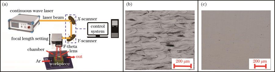
Fig. 1. Schematic of experimental equipment and sample surface morphologies. (a) Schematic of experimental equipment; (b) surface topography of low-roughness sample; (c) surface morphology of flannelette polishing sample
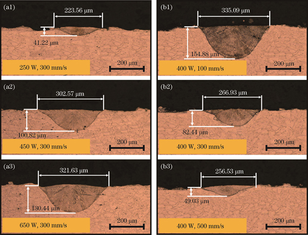
Fig. 2. Cross sections of single-channel laser polished pools under different parameters. (a1)-(a3) Different powers; (b1)-(b3) different scanning speeds
Fig. 3. Three-dimensional morphologies of single-channel laser polished pools under different parameters. (a1)-(a3) Different powers; (b1)-(b3) different scanning speeds
Fig. 4. Three-dimensional morphologies of single-channel polished surfaces under same energy density. (a) Laser power of 250 W and scanning speed of 300 mm/s; (b) laser power of 375 W and scanning speed of 450 mm/s; (c) laser power of 500 W and scanning speed of 600 mm/s; (d) laser power of 625 W and scanning speed of 750 mm/s
Fig. 5. Profiles of single-channel polished surfaces under same energy density. (a) Laser power of 250 W and scanning speed of 300 mm/s; (b) laser power of 375 W and scanning speed of 450 mm/s; (c) laser power of 500 W and scanning speed of 600 mm/s; (d)laser power of 625 W and scanning speed of 750 mm/s
Fig. 6. Cross sections and profiles of single-channel polished pools under same energy density. (a) Cross sections of single-channel polished pools; (b) profiles of single-channel polished pools
Fig. 7. Schematics of continuous laser single-channel polishing mechanism. (a) Heat input; (b) formation of molten pool; (c) surface melting flow; (d) solidification molding
Fig. 8. Three-dimensional morphologies of two-channel lap polished surfaces under different filling line spacings. (a) 0.01 mm;(b) 0.02 mm; (c) 0.04 mm; (d) 0.06 mm; (e) 0.08 mm
Fig. 9. Profiles of two-channel lap polished surfaces under different filling line spacings. (a) 0.01 mm; (b) 0.02 mm; (c) 0.04 mm;(d) 0.06 mm; (e) 0.08 mm
Fig. 10. Mechanism diagrams of continuous laser parabolic spacing affecting surface morphology. (a) Low line spacing; (b) high line spacing
Fig. 11. Surface topography and 3D surface topography after one laser polishing. (a) Surface topography; (b) three-dimensional surface topography
Fig. 12. Surface topography and 3D surface topography after two laser polishings under orthogonal scanning. (a) Surface topography; (b) three-dimensional surface topography
Fig. 13. Schematics of scanning strategy. (a) Final formed region; (b) schematic of scanning path
Fig. 14. Surface topography and 3D surface topography after four laser polishings under orthogonal scanning + unlapped area backfill scanning. (a) Surface topography; (b) three-dimensional surface topography
Fig. 15. Surface roughnesses under different scanning strategies
Fig. 16. Cross section and hardness after laser polishing. (a) Metallographic structure diagram of cross section; (b) hardness distribution
Fig. 17. Schematic of EDS line scanning of laser polished section
Fig. 18. Element distribution of Laser polished section
|
Table 1. Single channel polishing parameters
|
Table 2. Parameter table of single-channel laser polishing under same energy density
|
Table 3. Experimental parameters of two-channel lap polishing

Set citation alerts for the article
Please enter your email address
© Copyright 2018-2021 | Chinese Laser Press. All Rights Reserved 沪ICP备15018463号-20