
Hongyu Huang, Zhenming Yu, Liang Shu, Kaixuan Sun, Feifei Yin, Kun Xu, "Low-resolution optical transmission using joint shaping technique of signal probability and quantization noise," Chin. Opt. Lett. 21, 050602 (2023)
- Chinese Optics Letters
- Vol. 21, Issue 5, 050602 (2023)
Abstract
1. Introduction
With the development of 5G mobile broadband services and cloud services, data traffic is increasing dramatically. To meet the demand for increased data traffic, the capacity of optical networks needs to be extended further[1,2]. In order to achieve high-capacity transmission, it is necessary to improve the baud rate of transmission systems. As the baud rate increases, the bandwidth limitation (BWL) will severely affect the bit-error-rate (BER) performance of the system. Digital pre-emphasis (DPE) has been studied in optical transmission system to alleviate the impact of BWL[3]. In general, high-resolution digital-to-analog converters (DACs), which can convert digital signals to complex analog signals, are critical for employing effective DPE[4]. The physical number of bits (PNOB) describes the resolution of the DACs. A higher PNOB means less quantization noise. Increasing the PNOB could raise the signal-to-noise ratio (SNR) of the system and improve the BER performance. However, high-PNOB DACs significantly increase the costs of transmission system and are also not efficient in terms of power consumption. By comparison, low-resolution DACs have the advantage of being cost-effective and having low power consumption. Compared to the application specific integrated circuit (ASIC) power consumption of a metropolitan optical transmission system using 8-bit DACs/ADCs, the ASIC power consumption of a metropolitan optical transmission system using 4-bit DACs/ADCs will reduce by 20%[5]. Employing low-resolution DACs/ADCs has the potential to reduce the costs and power consumption of transmission systems, while the introduced quantization noise will cause a considerable impact on the system. A novel method, the digital resolution enhancer (DRE) method, is proposed to reduce the impact of quantization noise, which shows excellent performance in the low-resolution transmission experiment[6]. However, DRE faces the challenges of computational complexity and delay due to the application of the Viterbi algorithm[7]. The delta-sigma converter has also been studied to increase quantization resolution, but it requires a high oversampling rate[8]. Error feedback noise shaping (EFNS) improves the conventional delta-sigma converter, which does not require a high oversampling rate[9]. The conventional delta-sigma converter can still obtain shaping gain when the sample per symbol (SPS) is 1.1. EFNS shows comparable performance to the DRE while also having advantages of low computational complexity, low processing delay, and no required channel response[10–13].
Although the noise shaping technique can reduce the considerable impact of quantization noise, the performance of low-resolution systems is required to be further improved. In general, the quantizer can be viewed as a source of additive white noise[14,15]. It is well known that probabilistic shaping (PS) can provide significant gain in additive white Gaussian noise (AWGN) channels[16] and even larger improvement in nonlinear fiber channels[17]. Many ultra-high speed and long-distance optical transmission systems are implemented with the aid of PS[18–20]. Using PS to improve the ADC/DAC resolution tolerance has been studied in Ref. [21]. The research shows that PS can effectively reduce the BER of low-resolution transmission systems. In the work[22], the combination of PS and DRE is studied. The results show that PS can provide an SNR gain of 0.75 dB when DRE is employed.
In this paper, we extend our previous work[13] and propose a joint shaping technique for low-resolution optical transmission, which is experimentally verified in both intensity-modulation direct-detection (IM/DD) and coherent optical systems. More numerical and experimental results are also presented to give a deep analysis on the joint shaping technique. First, we confirm that the joint shaping can significantly improve the performance of the low-resolution IM/DD transmission system through a 40-Gbaud high-speed IM/DD experimental transmission system. The results show that a BER of 7% overhead hard-decision forward error correction (HD-FEC)
Sign up for Chinese Optics Letters TOC. Get the latest issue of Chinese Optics Letters delivered right to you!Sign up now
2. Methods
2.1. Error feedback noise shaping
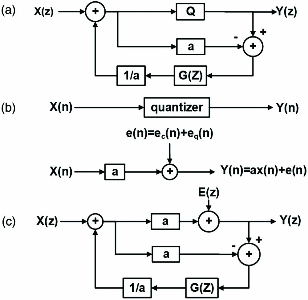
Figure 1(a) shows the
![]()
Figure 1.(a) Z-domain structure of the EFNS. (b) Linear model of clipping and quantization. (c) Z-domain structure of the EFNS based on a linear model.
In Eq. (1), the noise term is
The frequency domain shaping of the quantization noise
The problem of optimizing Eq. (3) can be solved by the linear optimization methods in mathematics. The specific calculation process is described in the reference[12].
Noise shaping minimizes the impact of quantization noise in the signal band. Figure 2 shows the quantization noise power spectral density (PSD) of 56-Gbaud 16QAM signals with a 4-bit quantizer. The sampling rate is 84 GSa/s. This illustrates that the noise in the signal band is reduced significantly by EFNS. The gain of in-band noise is 6.845 dB. A more detailed analysis of the EFNS can be found in our previous work[12].
![]()
Figure 2.Quantization noise of the PSD.
2.2. Probabilistic shaping
Conventional modulations support limited optimization options for many SNR values. PS is an effective technique in these scenarios, which shapes the probability of the constellation points to push the system performance closer to the Shannon’s limit. Input signals following Maxwell–Boltzmann (MB) distribution are often used[24,25], especially in the Gaussian channel.
The MB distribution follows the equation
Here, we use a constant composition distribution matcher (CCDM) to shape signals to the MB distribution[26]. The PS based on the MB distribution will give higher probabilities to inner points and lower probabilities to outer points, as shown in Fig. 3.
![]()
Figure 3.Constellations of the uniform signals and the PS signals.
From the view of technology, EFNS could improve the SNR of low-resolution systems by reducing the quantization noise in the signal band, while the PS could improve the performance of the system at a certain SNR. The SNR of the system is calculated before the symbol decision, which includes the overall system noise. Therefore, the relation between the two shaping techniques is that the optimal parameters of the PS will change with the improvement of the SNR caused by EFNS. Hence, the optimization of the joint shaping can be described as follows. First, the parameters of the EFNS should be optimized to improve the SNR of the system as far as possible. Then, the shaping degree of the PS is optimized according to the SNR of the system with EFNS. This will be discussed in detail in subsection 3.3.
3. Results
3.1. Performance in IM/DD system
We first conduct an experiment of 40-Gbaud IM/DD PAM4 transmission system to investigate the transmission performance of the joint shaping technique. The transmission distance is 3 km. Figure 4(a) shows the experimental setup. The DSP process at the transmitter (Tx-DSP) is shown in Fig. 4(b), where the roll-off factor of the square-root raised cosine (SRRC) filter is 0.1. The digital pre-emphasis (DPE) is an FIR filter, which is designed by calculating the inverse of the channel response[3]. In the experiment, 40-Gbaud PAM4 signals are generated by a 60-GSa/s arbitrary waveform generator (AWG, Keysight M8195A) with a 25-GHz bandwidth and amplified by a driver. Then, the signals are modulated by a Mach–Zehnder modulator (MZM) and transmitted through a 3-km stand single mode fiber (SSMF). At the receiver side, a variable optical attenuator (VOA) is employed to adjust the receiver optical power (ROP). The optical signals are detected by a photodetector (PD), and the electrical signals are received by a 50-GSa/s digital sampling oscilloscope (DSO, Tektronix DSA72504D) with 25-GHz bandwidth. The received signals are processed by the DSP at the receiver (Rx-DSP), which is shown in Fig. 4(c), where a linear feed-forward equalizer (FFE) with 91 taps is utilized to equalize the channel distortion.
![]()
Figure 4.(a) Experimental setup of the IM/DD PAM4 transmission. (b) DSP flow in the transmitter. (c) DSP flow in the receiver. PRBS, pseudo-random binary sequence.
The relationship between the BER and the PNOB for the four kinds of signals (uniform PAM4, PS-PAM4, uniform PAM4 with EFNS, and PS-PAM4 with EFNS) is shown in Fig. 5(a), where the entropy of PS-PAM4 is 1.9815 bits/symbol, and the ROP is
![]()
Figure 5.(a) BER vs. PNOB when the ROP is −3 dBm. (b) BER vs. ROP when the PNOB is 3. (c) BER vs. ROP when the PNOB is 4.
3.2. Performance in coherent system
An experiment of a 30-Gbaud DP-16QAM transmitting over an 80-km SSMF is conducted to further verify the performance of joint shaping in the coherent transmission. Figure 6(a) is the experimental setup. The DSP flow in the transmitter is shown in Fig. 6(b), where the roll-off factor of SRRC is 0.1. The DPE is an FIR filter, which is designed according to the inverse of the channel response[3]. After Tx-DSP, signals are generated by a 60-GSa/s arbitrary waveform generator (Keysight M8195A) with a 25-GHz bandwidth. Then, the signals are amplified by a diver and modulated by a double-polarization in-phase/quadrature (DP-IQ) modulator. The launched optical power of transmission is 2 dBm. The optical signals are transmitted through an 80-km SSMF. After transmission, the optical signals are received by the integrated coherent receiver and collected by a digital storage oscilloscope (Tektronix DSA72504D) with a 25-GHz bandwidth. The power and wavelength of the local oscillator (LO) laser are 11 dBm and 1550 nm, respectively. After that, the signals are processed by Rx-DSP, which is shown in Fig. 6(c).
![]()
Figure 6.(a) Experimental setup of the coherent DP-16QAM transmission process. (b) DSP process at the transmitter. (c) DSP process at the receiver. CD, chromatic dispersion; CMA, constant modulus algorithm; CPR, carrier phase recovery; DD-LMS, decision directed least mean square; LO, local oscillator.
The transmission performance of four kinds of signals (uniform 16QAM, PS-16QAM, uniform 16QAM with EFNS, and PS-16QAM with EFNS) under a different PNOB is investigated, where the entropy of the PS-16QAM is 3.963 bits/symbol. The relationship between the BER and the PNOB is shown in Fig. 7(a), where the optical signal-to-noise ratio (OSNR) is 30 dB. This shows that when the PNOB is 3 or 4, the joint shaping can obtain significant performance improvement. Figure 7(b) shows the relationship between the OSNR and the BER when the PNOB is 3. A BER of
![]()
Figure 7.(a) BER vs. PNOB when the OSNR is 30 dB. (b) BER vs. OSNR when the PNOB is 3. (c) BER vs. OSNR when the PNOB is 4.
3.3. Optimization of the shaping degree
To maximize the gain of the joint shaping technique, the shaping degree needs to be optimized. Because optical transmission systems perform like an AWGN channel in the linear region[27], the shaping degree optimization problem can refer to the problem in the AWGN channel. The generalized mutual information (GMI) under a different SNR and PS degree in the AWGN channel is shown in Fig. 8(a), which is normalized under each SNR according to Eq. (6). The range of the normalized GMI value is from 0 to 1, where 0 represents the lowest GMI under a certain SNR within the testing shaping degree range, and 1 represents the highest GMI,
![]()
Figure 8.(a) GMI performance under different SNRs and PS degrees, which have been normalized to each SNR (The value ranges from 0 to 1, where 0 represents the lowest GMI, and 1 represents the highest GMI). (b) The SNR and the MI of the signals without EFNS. (c) The SNR and the MI of the signals with EFNS.
The optimized shaping degree depends on the SNR of the systems. Thus, we design the following steps for the optimization of the shaping degree. First, the SNR of the system is measured, which is calculated based on the demodulated signals and includes all noise of the transmission system. Second, the shaping degree is obtained according to the optimal shaping degree of the corresponding SNR. Third, the optimized PS degree can be applied.
Simulations are performed to illustrate and verify the given steps. The parameters of the simulation system remain consistent with the 30-Gbaud/s coherent experimental system. The PNOB is set to 3. The transmission distance is 80 km. The OSNR of the system is 17 dB. Uniform 16QAM signals and three kinds of PS signals, i.e., PS1-16QAM (3.963 bits/symbol), PS2-16QAM (3.898 bits/symbol), and PS3-16QAM (3.85 bits/symbol), are transmitted. First, we transmit signals and calculate the SNR of the system. Figure 8(b) shows that the SNR of the system is about 11.3 dB when EFNS is not used. According to Fig. 8(a), the optimal shaping degree is around 3.9 bits/symbol when the SNR is about 11.3 dB. Then, a PS degree of 3.9 bits/symbol can be designed for transmission. The numerical results in Fig. 8(b) verify the above design. The mutual information (MI) of the PS2-16QAM signal (3.898 bits/symbol) can reach 3.426 bits/symbol, which is the highest among the tested signals.
After EFNS, the SNR of the system is increased to about 12.5 dB, as shown in Fig. 8(c). The SNR of the system is improved by 1.2 dB by the EFNS, which is irrelevant to the PS. According to Fig. 8(a), the optimal shaping degree is around 3.96 bits/symbol when the SNR is 12.5 dB. The numerical results in Fig. 8(c) show that the MI of the PS1-16QAM signal (3.963 bits/symbol) can reach 3.6663 bits/symbol, which is the highest among the tested signals. The above results indicate that the proposed optimization scheme is effective.
3.4. Comparison between the combined PS and DRE and the joint shaping
The simulations are performed to do a comparison between the combined PS and DRE and the joint shaping. The simulation system is the 30-Gbaud coherent transmission system mentioned in subsection 3.3. The parameters of the simulation system remain consistent with the 30-Gbaud/s coherent experimental system. The results are shown in Fig. 9. The performance of the joint shaping is slightly worse than that of the combined PS and DRE at a PNOB of 3 and close to that of the combined PS and DRE at a PNOB of 4. In conclusion, compared with the combined PS and DRE, the proposed joint shaping can show comparable performance but has disadvantages of complexity and processing delay.
![]()
Figure 9.Comparison between the combined PS and DRE and the joint shaping.
4. Conclusion
In conclusion, we propose a joint shaping technique, i.e., combining PS and EFNS, to improve the performance of low-resolution optical transmission for the first time, to the best of our knowledge. First, we conduct a 40-Gbaud IM/DD experimental transmission system to verify the proposed method. The results show that the joint shaping can improve the performance of system effectively. Thanks to the joint shaping, the BER of the system can easily achieve an HD-FEC threshold with a 3-bit quantizer. We also establish a 30-Gbaud coherent experimental transmission system to verify the performance of the joint shaping in the coherent system. The results show that significant performance improvement is obtained through the effective jointing. The BER of the system can reach below
References
[4] Y. Yoffe, E. Wohlgemuth, D. Sadot. Digitally enhanced DAC: low-resolution digital pre-compensation for high speed optical links. Optical Fiber Communication Conference (OFC), 1(2018).
[6] Y. Yoffe, E. Wohlgemuth, D. Sadot. Low resolution pre-compensation for DCI based on dynamic quantization. Advanced Photonics (BGPP, IPR, NP, NOMA, Sensors, Networks, SPPCom, SOF), SpM2G.3(2018).
[8] I. Galton. An analysis of quantization noise in delta sigma modulation and its application to parallel delta sigma modulation(1992).
[9] K. Bai, Z. Luo, D. Zou, W. Wang, Q. Sui, X. Tang, F. Li, Z. Li. Quantization noise suppression with noise-shaping technique in DMT-modulated IM/DD optical interconnects utilizing low-resolution DAC. Optical Fiber Communications Conference and Exhibition (OFC), W6A.19(2021).
[10] L. Shu, Z. Yu, K. Sun, Z. Wan, H. Huang, K. Xu. Error-feedback noise shaping for low-resolution high-speed IM/DD and coherent transmission systems. Optical Fiber Communications Conference and Exhibition (OFC), W7F.5(2021).
[13] H. Huang, Z. Yu, L. Shu, K. Sun, Q. Yin, K. Xu. Joint shaping technique of signal probability and quantization noise for coherent transmission systems. Asia Communications and Photonics Conference (ACP), T4A.70(2021).
[18] A. Ghazisaeidi, I. F. de J. Ruiz, R. Rios-Muller, L. Schmalen, P. Tran, P. Brindel, A. C. Meseguer, Q. Hu, F. Buchali, G. Charlet, J. Renaudier. 65 Tb/s transoceanic transmission using probabilistically-shaped PDM-64QAM. 42nd European Conference on Optical Communication, 1(2016).
[20] S. Chandrasekhar, B. Li, J. Cho, X. Chen, E. Burrows, G. Raybon, P. Winzer. High-spectral-efficiency transmission of PDM 256-QAM with parallel probabilistic shaping at record rate-reach trade-offs. 42nd European Conference on Optical Communication, 1(2016).
[22] M. Abu-Romoh, T. T. Nguyen, Y. Yoffe, I. Phillips, W. Forysiak. Numerical study on the combination of probabilistic shaping and digital resolution enhancer for high baud rate optical communications. European Conference on Optical Communications (ECOC), 1(2020).
[27] A. Carena, G. Bosco, V. Curri, P. Poggiolini, M. T. Taiba, F. Forghieri. Statistical characterization of PM-QPSK signals after propagation in uncompensated fiber links. 36th European Conference and Exhibition on Optical Communication, 1(2010).


Set citation alerts for the article
Please enter your email address

© Copyright 2018-2021 | Chinese Laser Press. All Rights Reserved 沪ICP备15018463号-20