1Anhui Provincial Key Laboratory of Photonics Devices and Materials, Anhui Institute of Optics and Fine Mechanics, Chinese Academy of Sciences, Hefei 230031, China
2Advanced Laser Technology Laboratory of Anhui Province, Hefei 230037, China
3State Key Laboratory of Pulsed Power Laser Technology, National University of Defense Technology, Hefei 230037, China
Jingzhen Shao, Xu Liang, Libing You, Ning Pan, Ying Lin, Shimao Wang, Zanhong Deng, Xiaodong Fang, Xi Wang, "Laser-induced damage and periodic stripe structures of a CaF2 single crystal by an ArF excimer laser," Chin. Opt. Lett. 18, 021403 (2020)
Copy Citation Text
The laser-induced damage threshold of a calcium fluoride (CaF2) single crystal was obtained by a 193 nm ArF excimer laser. The damage morphology of the crystal was analyzed. The results showed that the surface of CaF2 single crystal broke along the natural cleavage plane under ArF excimer laser irradiation, some fragments fell off, and Newton’s rings were observed on the curved fragments. Laser-induced periodic stripe structures (LIPSS) appeared on the surface layer beneath the fragments that peeled off. The spacing of LIPSS was measured, and the formation mechanism of LIPSS was analyzed based on the interference model.
Calcium fluoride () crystals have become an important optical material for ultraviolet (UV) and deep UV (DUV) lithography, UV optical systems, and high power laser devices, due to their remarkable optical features in the UV range, high chemical resistance against halogen gas, as well as the very low value of the nonlinear refractive index[1–5]. As a key optical component, laser-induced surface damage and failure of crystals has become a fundamental issue. In order to ensure the effective application of optical components in laser systems, it is necessary to understand the interaction process and mechanism between the laser and crystals, improve the laser damage resistance of crystals, and prolong the life of laser systems.
So far, many valuable researches in the fields of optical properties[6,7], laser processing[8,9], and laser-induced damage[10–20] of crystals have been done. The results show that the laser-induced damage of crystals is a complex process, which is closely dependent on the irradiation characteristics of the laser, including laser wavelength, pulse width, repetition frequency, average power, etc., as well as the crystal characteristics, especially surface processing techniques. Azumi et al.[13] investigated the relationship between crystal structure, laser durability, and laser-induced damage threshold (LIDT) and determined the position of the crystal orientation of relative to the polarization plane of the ArF excimer laser that produced the highest LIDT. Li et al.[14] systematically studied surface damage and the material failure mechanism of the single crystal by 355 nm/6.8 ns laser pulses. Laser-induced periodic stripe structures (LIPSS) were observed at the crystal surface under femtosecond (fs)[15] or picosecond (ps) laser[16] irradiation.
In this Letter, we reported the damage of crystals materials after 193 nm ArF excimer laser irradiation. LIPSS were observed at the nanosecond excimer laser irradiation process of crystal materials. The laser damage threshold and damage morphology of crystals were analyzed.
Sign up for Chinese Optics Letters TOC. Get the latest issue of Chinese Optics Letters delivered right to you!Sign up now
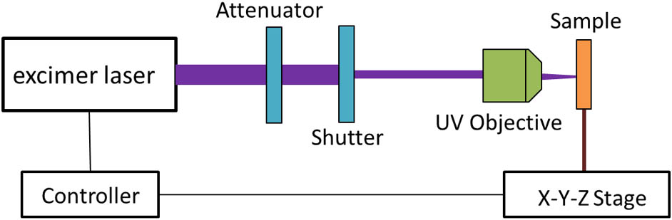
The laser damage test apparatus is shown in Fig. 1. The experiment was carried out in a standard atmospheric environment. The ArF excimer laser produced by our institute was used as a light source system. The laser has a wavelength of 193 nm, pulse duration of about 20 ns, an initial spot size of , and a flat top beam profile. The laser beam was applied vertically to the crystal after passing through the attenuator, the shutter, and the UV objective. A laser spot with a diameter of μ was shaped at the crystal plane. The excimer laser system and the three-dimensional (3D) mobile platform could be operated simultaneously by the control system.
Figure 1.Experimental setup for laser-induced damage test.
The sample was a UV-grade single crystal produced by Qinhuangdao Intrinsic Crystal Technology Co., Ltd., with a diameter of 30 mm, a thickness of 2 mm, and double-sided polishing. The damage threshold of the sample was obtained by the “one-on-one” test method, that is, each unexposed site on the surface of the sample was exposed to a single laser pulse with defined beam parameters. Then, the laser beam was moved to the next unexposed site no matter whether the damage occurred or not. Fifteen sites were exposed to one preselected pulse energy and record, and, for each site, the actual pulse energy was measured by the beam diagnostic unit as well as the state of damage after irradiation. This sequence was repeated for other pulse energies. Figure 2 shows the exposed sites of the sample and the corresponding laser fluence. The red dot represents the damaged exposed site, and the white dot represents the undamaged exposed site. The test was carried out from the bottom of the sample row by row to the top of the sample (irradiated in the order of ), thus minimizing the impact of laser irradiation on the unexposed sites.
Figure 2.Exposed sites of samples and the corresponding laser fluence.
The damage images of the sample were obtained by an Olympus BX51M optical microscope, and the microstructure of the damage spot was tested by a TESCAN VEGA 3 scanning electron microscope. Damage threshold data were obtained by the damage probability method, which is described in the International Organization for Standardization (ISO) standard 21254-2[17]. The damage probability was determined for each laser fluence by calculating the ratio of the number of damaged sites to the total number of sites tested. A plot of the damage probability versus laser fluence was constructed. The damage probability data are linearly extrapolated to the X axis, where it corresponds to zero damage probability. The laser fluence corresponding to zero damage possibility is the damage threshold. Figure 3 shows the damage probability plot of a sample. Linear extrapolation of the damage probability data to zero damage probability yielded a damage threshold of .
Figure 3.Damage probability plot, damage threshold .
Figure 4 shows an optical micrograph of the damage site of the sample at different laser fluence. The results showed that the damage area of the single crystal increases gradually with the increase of laser fluence. Under the pulsed laser irradiation, the crystal surface was partially removed in the form of large fragments whose shape represented the cleavage planes of the crystal. Meanwhile, the colored interference fringes were observed on the surface.
Figure 4.Optical micrograph of the damage site for different laser fluence.
Figure 5(a) shows an optical micrograph of the sample at the laser fluence of . The obvious interference fringe/Newton’s ring pattern was observed, which was formed by the interference of reflected light on the curved fragments and on the plane of the sample. A similar phenomenon was also observed on crystals irradiated with a 248 nm excimer laser[18]. It means that the thickness of the curved fragments is uniform. The radii of the interference dark ring obey the formula where is the order of the ring, is the wavelength of the light used for observation, and is the radius of curvature. Since the white light source was used in the experiment, Newton’s ring pattern appeared multi-colored. The average wavelength of 580 nm was used for the analysis, and the curvature radius of the fragment was obtained by the dark ring radius. Figure 5(c) shows the scatter plots of the order and radius of dark rings with four fragments [a, b, c, d in Fig. 5(a)]. Figure 5(d) shows the origin of the ring pattern. Using Eq. (1) and the measured sizes of the interference dark ring, the radii of curvature for the four fragments were calculated to be 47.16, 45.16, 39.63, and 35.84 μm, respectively. The different radii of curvature indicate the different degree of warping.
Figure 5.(a), (b) Optical damage micrograph for the laser fluence of . (c) Analysis of Newton’s rings for the four fragments [a, b, c, d in (a)]. (d) The origin of the ring pattern.
In order to further understand the damage mechanism of the single crystal by the 193 nm ArF excimer laser, scanning electron microscopy (SEM) was employed. The surface damage morphologies of the sample under the laser fluence of , , , and are shown in Fig. 6. Under the pulse laser irradiation, the surface of the single crystal broke along the natural cleavage plane, and the surface was partially removed in form of strip-shaped fragments. The strip-shaped fragments were different in length. No heat melting was observed. Similar morphologies were also found at the 248 nm KrF laser irradiation process[19,20], as well as at the 193 nm ArF laser irradiation of the single crystal[21].
Figure 6.SEM image of the laser-irradiated under different laser fluence at (a) , (b) , (c) , and (d) .
Generally, in a transparent material, there is less intrinsic absorption of incident laser light, which is not enough to directly damage materials. For optical material damage, the laser energy must be deposited into the material by promoting electrons from the valence band to the conduction band. The nonlinear absorption mechanisms, such as multiphoton absorption, electron avalanche ionization, and impurity defect absorption play a key role in the processing of laser-induced damage to transparent materials. The peeling off of strip-shaped fragments may be due to the local heating caused by the above mechanisms, which results in larger mechanical stress and the fracture along the crystalline axis.
LIPSS were observed under different laser fluence irradiations, and LIPSS appeared in the surface layer beneath the fragments that were peeled off. The stripes were elongated or annular and were related to the shape of the fragments stripped. LIPSS have been reported by many researchers. Birnbaum[22] first reported the formation of LIPSS on a semiconductor surface by ruby lasers. He attributed this phenomenon to the diffraction effects produced at the focus of a lens and suggested that the grooves were produced by the removal of material at the positions of maximum electric field intensity. Emmony et al.[23] proposed the concept of surface scattering centers. They suggested that LIPSS were generated via interference between the incident laser and the scattered light at surface defects and scratches. Based on the interference theory, the following model was established: where is the spacing of the fringes, is the wavelength of the incident light, and is the angle of incidence.
Some elongated LIPSS were randomly selected and measured, as the LIPSS of I-IX in Fig. 6. The data are listed in Table 1. The results showed that the spacing of periodic fringes is different. The lowest value of 153 nm was lower than the laser wavelength of 193 nm, while the highest value of 654 nm was more than three times the laser wavelength of 193 nm. Moreover, the laser fluence had almost no influence over the spacing of the periodic stripe. As long as the laser energy was enough to peel off the surface layer of the sample, it was possible to form LIPSS.
No.
I
II
III
IV
V
VI
VII
VIII
IX
Laser fluence (J/cm2)
7.34
7.34
7.34
6.60
6.60
5.75
4.53
4.53
4.53
Fringe spacing (nm)
453
296
548
403
627
654
202
386
153
Table 1. Laser Fluence and Fringe Spacing of LIPSS
So far, there is no unified theoretical explanation for the formation mechanism of LIPSS. The generally accepted theory is that the interference between the incident laser beam and the electromagnetic wave produces a modulation of the laser intensity on the material surface. The temperature of the sample surface rises fastest where the light intensity is strong. Driven by the surface tension, the high temperature liquid will obviously move toward the low temperature zone, thus forming a regular periodic structure. The spacing of the interference fringes is given by Eq. (2). In our experiment, the laser beam was perpendicular to the surface of the sample (), so the fringe spacing should be equal to the laser wavelength, i.e., . But, the results did not agree with it.
Further analysis revealed that although the spacing of elongated LIPSS varied, the spacing of the stripe at the beginning of LIPSS was almost the same, as shown in Fig. 7. The spacing of the labeled fringes I–V was 173 nm, 260 nm, 226 nm, 177 nm, and 220 nm, respectively. The average spacing was 211 nm, which was close to the laser wavelength of 193 nm. It was inferred that the beginning of LIPSS conformed to the interference mechanism.
Figure 7.SEM image of the laser-irradiated under .
The formation of LIPSS is a complex nonlinear process, which may involve various mechanisms such as laser interference theory[22–25], surface guided wave theory[26], laser-driven acoustic wave theory[27], and thermal and fluid mechanics theory[28]. These mechanisms are closely related to the laser parameters and material properties, including the incident angle, polarization, wavelength, frequency, and energy of the pulse laser and the surface defect, the light absorption, and electromagnetic properties of the materials. The dominant mechanism depends on the specific experimental conditions.
In our experiments, LIPSS appeared in the surface layer below the fragments that peeled off, which indicated that the formation of LIPSS was related to the peeling of the fragments. It had been analyzed that the surface layer of the sample was warped under laser irradiation, and interference fringes appeared due to the interference between reflected light on the warped surface and on the plane. Therefore, it was assumed that the formation of LIPSS may be related to the warping layer. Meanwhile, the surface layer of the sample vaporized and ionized to form plasma by defect absorption and two-photon absorption under laser irradiation. The plasma expanded and exploded to produce a shock wave, which led to the change of spatial intensity on the sample surface. We suggested that the formation of LIPSS was also related to the effect of the plasma shock wave on the material surface.
In conclusion, the laser-induced crystal damage threshold by the 193 nm ArF excimer laser was obtained. The formation mechanism of the color interference fringes on the surface of the material was analyzed. LIPSS of the crystal induced by an excimer laser were reported. The results showed that the 193 nm ArF excimer LIDT of the crystal was . The color interference fringe/Newton’s ring pattern formed by the interference of reflected light on the warped surface and on the plane and the radius of curvature of the warped surface were calculated. Under laser irradiation, the surface layer of crystals fell off along the cleavage plane, and LIPSS appeared in the surface layer below the fragments that peeled off. The formation of LIPSS may be related to the interference mechanism and the plasma shock wave on the material surface.
[17] Lasers and laser-related equipment—Test methods for laser-induced damage threshold—Part 2: Threshold determination. International Organization for Standardization(2011).
Jingzhen Shao, Xu Liang, Libing You, Ning Pan, Ying Lin, Shimao Wang, Zanhong Deng, Xiaodong Fang, Xi Wang, "Laser-induced damage and periodic stripe structures of a CaF2 single crystal by an ArF excimer laser," Chin. Opt. Lett. 18, 021403 (2020)