
Kejun Shang, Ming Lei, Qiang Xiang, Yonglin Na, Lizhe Zhang, Huaiyong Yu, "Near-navigation-grade interferometric fiber optic gyroscope with an integrated optical chip," Chin. Opt. Lett. 18, 120601 (2020)
- Chinese Optics Letters
- Vol. 18, Issue 12, 120601 (2020)
Abstract
Interferometric fiber optic gyroscopes (IFOGs) were developed for decades before their performance became sufficient for commercial use[
Multi-functional integrated optical modulator chips (IOMCs), which include a polarizer, Y-junction, and PM for closed-loop operation, have been widely used in IFOGs[
Using discrete optical components not only increases the size of IFOGs but also results in parasitic reflections, which increase insertion losses at fusing points[
Sign up for Chinese Optics Letters TOC. Get the latest issue of Chinese Optics Letters delivered right to you!Sign up now
An IOC integrating an SLD, PD, and coupler is proposed for IFOG application in this work. We describe the design of the IOC, sample fabrication, and testing of the optical power, linewidth, and central wavelength. An IFOG prototype based on IOC was assembled, and the bias instability and scale factor were tested under coils of different length. The bias instability was low at 0.018 deg/h, which demonstrates that the primary performance of the IOC can satisfy the requirements of a near-navigation-grade IFOG.
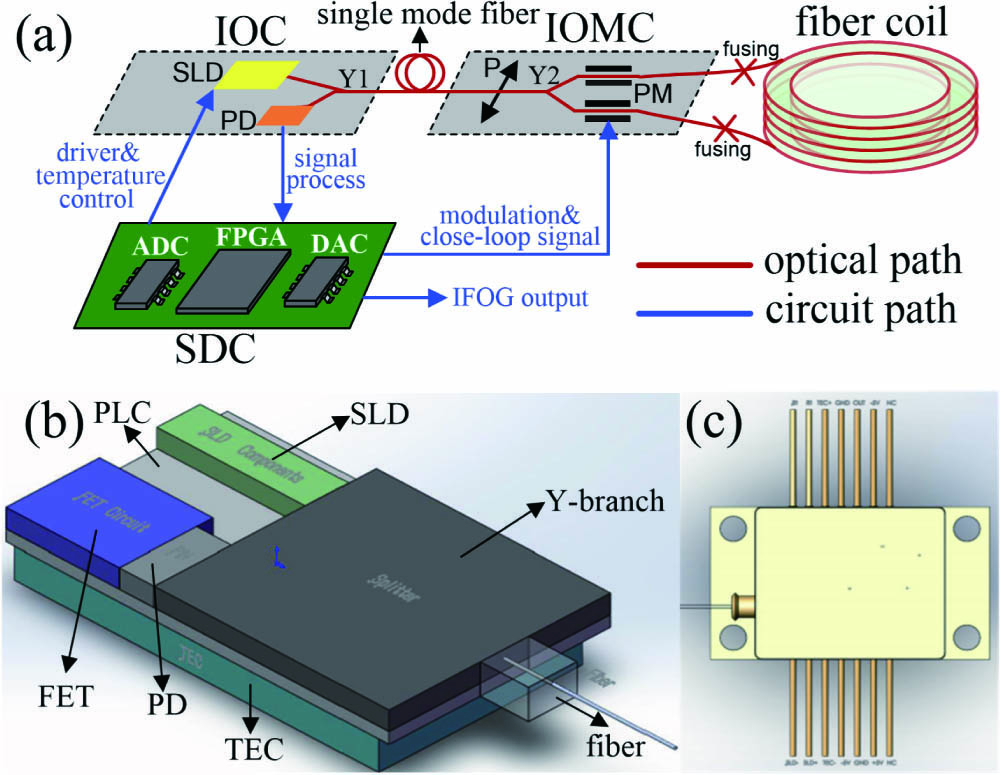
The schematic configuration of the IFOG based on IOC is shown in Fig.
![]()
Figure 1.(a) Schematic illustration of the IFOG based on an IOC. IOC, integrated optical chip; IOMC, integrated optical modulator chip; SDC, signal detection circuit; SLD, superluminescent diode; PD, photodiode; Y1/Y2, Y-branch; P, polarizer; PM, phase modulator; ADC/DAC, analog-to-digital/digital-to-analog converter; FPGA, field-programmable gate array. (b) Configuration of the IOC layout and (c) IOC package structure.
To improve the manufacturability and performance of the IFOG while reducing its cost, a multiple optical component packaging technology was used to provide electrical interconnection and light coupling between the optical components to ensure that the optical device operates optimally. In addition, a thermo-electric cooler (TEC) was used to maintain efficient thermal expansion between the SLD and submounts, which can result in significantly increased lifetime.
An epoxy attachment is generally considered the lowest-cost attachment process for building photonic devices. It is commonly used in photonic device proof-of-concept demonstration builds and early prototype builds because of its ease of use, low cost, and availability. Here, all of the optical components, including the TEC, SLD, field effect transistor (FET), and PD were attached by epoxy to the substrate to ensure the module’s performance and reliability. The configuration layout of the IOC is illustrated in Fig.
By designing a large-pitch silicon dioxide planar optical waveguide circuit (PLC)-type Y-branch chip, sufficient space is provided for the integration of the SLD and PD. The SLD is suitable for use with gyroscopes due to its large operational bandwidth. To expand its bandwidth, we adopted the dual quantum well design to expand the bandwidth of the III-V gain medium. An optical surface-matching SLD chip was mounted into a PLC through chip-to-chip coupling techniques. The main aim is to realize low-loss, high-integration coupling between the SLD chip and Y-branch chip. To increase the coupling efficiency and improve the signal-to-noise ratio (SNR) of the IFOG, a tapered mode conversion waveguide was optimized, and high-precision passive alignment was used. The process tolerance requirements are all within 1 μm because the sizes of the chip waveguide end-faces are all in the order of micrometers.
The next chip in the IOC is the PD chip. InGaAs was bonded to an InP substrate by a wafer bonding process with low dark current, high responsivity, and high reliability. The
The Y-branch Y1 is a 3 dB passive waveguide coupler made with doped
The IOC also contains a coupling-out structure, which provides light coupling into and out of the sensing coil. A semi-automated pigtailing process for the PM fiber was developed that uses a micro-machined polish-cut process with a dicing saw to fabricate the end-face. Then, automatic coupling alignment was realized to improve the coupling efficiency between the fiber and the IOC waveguide. In order to suppress back-reflection noise, the surface of the waveguide was optimized to a tilted angle. Eventually, suitable curing glue was used to strengthen the coupling package structure, significantly improving the strength and reliability of the IOC.
The IOC, with a small size of
Another key enabling component for an IFOG is the IOMC, which has multiple functions and is typically fabricated from lithium niobate. The lithium niobate quad-PM array chip uses previously developed state-of-the-art IOC chip design and fabrication techniques, primarily inductively coupled plasma (ICP) etching, proton exchange, and annealing. Polarizer P filters out cross-coupled erroneous signals in the light returning from the sensing coil by eliminating the transverse magnetic (TM) mode with a high polarization extinction ratio (PER). Y-branch Y2 is a 3 dB passive waveguide coupler based on a common substrate of lithium niobate. The physical size of the packaged IOMC is
Because of the limited rejection of the common base waveguide that acts as the spatial filter in the IOMC, a single-mode fiber (that can be seen as an absorber or a filter) is used to eliminate the anti-symmetrical mode radiating from the Y-junction, thereby ensuring optic reciprocity and improving the IFOG’s performance.
According to the integrated optical design and fabrication techniques shown in Fig.
![]()
Figure 2.IFOG prototype based on an IOC.
| IOC | Performances | Values |
|---|---|---|
| SLD | Optical power (μW) | 149 |
| Central wavelength (nm) | 1300.21 | |
| Linewidth (nm) | 41 | |
| Extinction ratio (dB) | 0.3 | |
| PD | Responsivity (A/W) | 0.88 |
| 3 dB bandwidth (MHz) | 6 | |
| Noise voltage (mV) | 0.49 | |
| Coupler | Splitting ratio | 50.6:49.4 |
| Power consumption (W, | 1.26 | |
Table 1. Measured Results of the IOC
An IFOG prototype based on the pigtailed IOC was successfully fabricated, as shown in Fig.
To compare IOC performances for IFOG application, sensing coils with different lengths and diameters were made of thin-clad polarization-maintaining fiber with dimensions of 80/135 μm. The detailed configurations of the two IFOGs are listed in Table
| IFOG | #1 | #2 | #3 |
|---|---|---|---|
| Average diameter (cm) | 3.8 | 4.5 | 4.5 |
| Fiber length (m) | 270 | 500 | 500 |
| Measured scale factor | 17,000 | 37,000 | 37,000 |
| Measured in-run bias instability (deg/h) | 0.13 | 0.018 | 0.0073 |
| ARW ( | 0.1 | 0.014 | 0.0033 |
Table 2. Measured Results of the IFOGs Based on an IOC
The scale factor of the IFOGs was calibrated on a precision rate table at room temperature. The in-run bias instability of the two IFOGs was obtained via Allan variance analyses of the noise data collected, as shown in Fig.
![]()
Figure 3.Bias instabilities of IFOGs with IOC and discrete optical components.
The biases of the IFOGs with IOC and discrete optical components were measured over a temperature range of
![]()
Figure 4.IFOG bias versus temperature.
As can be seen from Fig.
The test results were fully comparatively analyzed. The performance of the IFOG with IOC was mainly limited by photon, electron, and magnetic cross-coupling due to the chip-scale size, which caused a low SNR and poor accuracy.
In conclusion, we have proposed and demonstrated a near-navigation-grade IFOG based on IOC. It allows for a reduction in the SWaP-C of navigation-grade gyros used for engineering. Future work will conduct more characterization of the circuit design to suppress noise and limitations, which will be beneficial for improving the next generation of IFOGs. Furthermore, with proper integration modifications, an IOC and an IOMC will be integrated into a single chip. Technologies that eliminate the anti-symmetrical mode radiating from the Y-branch should be considered to ensure reciprocity and improve IFOG performance. We will report the results of this ongoing work in a future publication.
References
[1] H. C. Lefevre. The Fiber-optic Gyroscope(2014).
[2] J. Oliver. J. Navig., 9, 3(2007).
[3] Z. Pan, C. Zhang, C. Xie, Y. Zheng, H. Li, J. Tang, J. Liu. Chin. Opt. Lett., 16, 040601(2018).
[4] J. Scheuer. Opt. Lett., 34, 1630(2009).
[5] R. A. Bergh, L. Arnesen, C. Herdman. Proc. SPIE, 9852, 98520E(2016).
[6] N. Liu, Y. Niu, L. Feng, H. Jiao, X. Wang. Chin. Opt. Lett., 16, 010608(2018).
[7] R. Luo, Y. Li, S. Deng. Opt. Lett., 43, 4(2018).
[8] B. Wu, Y. Yu, X. Zhang. Sci. Rep., 9, 12946(2019).
[9] P. P. Khial, A. D. White, A. Hajimiri. Nat. Photon., 12, 671(2018).
[10] D. Blumenthal, 347.
[11] B. Wu, Y. Yu, J. Xiong, X. Zhang. Sci. Rep., 8, 8766(2018).
[12] S. Gundavarapu, M. Belt, T. Huffman, M. A. Tran, T. Komljenovic, J. E. Bowers, D. J. Blumenthal. Proc. SPIE, 10323, 103231A(2017).
[13] W. Li, Y. Gao, L. Tong. IEEE Photon. Tech. Lett., 31, 18(2019).
[14] J. Daenicke, M. Lämmlein, F. Steinhübl, D. W. Schubert. e-Polymers, 19, 330(2019).
[15] J. Jin, J. He, K. Ma, L. Kong(2019).
[16] T. Lei, H. Zhang, Y. Dong. Opt. Lett., 41, 729(2016).
[17] C. Croker, G. W. Keith, N. G. Tarleton. European Patent EP 2,762,833(2019).
[18] D. Olaf, D. Georg, K. Stefan, M. Tim, V. Sven, Z. Steffen. Sensors, 17, 567(2017).
[19] R. Bi, L. Miao, T. Huang, G. Ying, S. Che, X. Shu. Sensors, 19, 2851(2019).
[20] K. Yang, D. Oh, S. Lee, Q. Yang. Nat. Photon., 12, 5(2017).
[21] B. Chen, H. Wu, C. Xin, D. Dai, L. Tong. Nat. Commun., 8, 20(2017).
[22] L. Zachary, M. Vincent, D. Tara. Optica, 6, 5(2019).
[23] W. Bischel, M. Kouchnir, M. Bitter. Proc. SPIE, 8164, 81640Q(2011).
[24] M. A. Tran, T. Komljenovic, J. C. Hulme, M. J. Kennedy, D. J. Blumenthal, J. E. Bowers. Opt. Express, 25, 4(2017).
[25] L. Wang, D. Halstead, T. Monte(2019).
[26] S. Srinivasan, R. Moreira, D. Blumenthal, J. Bowers. Opt. Express, 22, 24988(2014).
[27] R. A. Bergh, H. Lefevre, H. Shaw. Opt. Lett., 7, 6(1982).


Set citation alerts for the article
Please enter your email address

© Copyright 2018-2021 | Chinese Laser Press. All Rights Reserved 沪ICP备15018463号-20