• Chinese Optics Letters
  • Vol. 19, Issue 10, 100501 (2021)
Jinxing Li1, Yueyi Yuan1, Qun Wu1, Shah Nawaz Burokur2, and Kuang Zhang1、*
Author Affiliations
  • 1Department of Microwave Engineering, Harbin Institute of Technology, Harbin 150001, China
  • 2LEME, UPL, Université Paris Nanterre, F92410 Ville d’Avray, France
  • show less
    DOI: 10.3788/COL202119.100501 Cite this Article Set citation alerts
    Jinxing Li, Yueyi Yuan, Qun Wu, Shah Nawaz Burokur, Kuang Zhang. Dual-band independent phase control based on high efficiency metasurface [Invited][J]. Chinese Optics Letters, 2021, 19(10): 100501 Copy Citation Text show less
    Schematic structures of the proposed meta-atom with the different geometrical details.
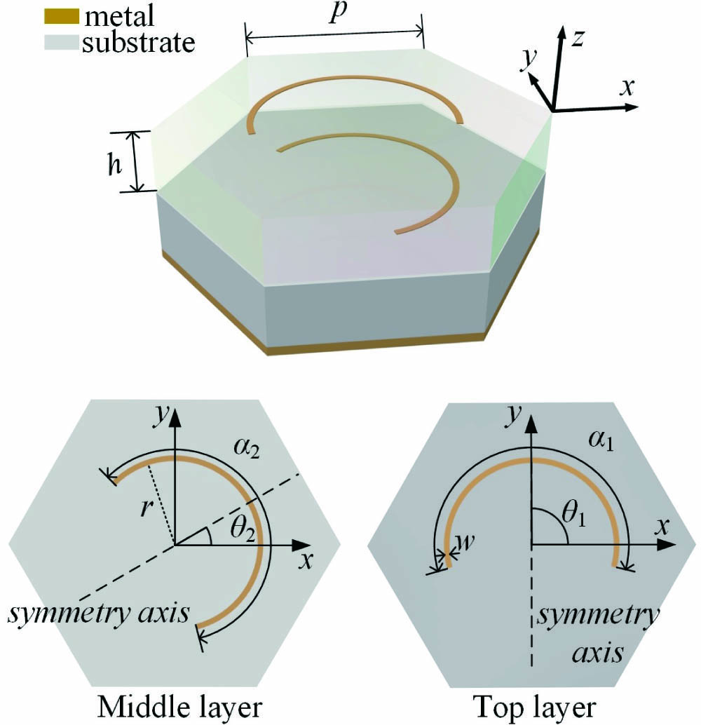
    Fig. 1. Schematic structures of the proposed meta-atom with the different geometrical details.
    Co-polarized reflection coefficient r++ for different values of θ1. (a) Simulated magnitude, (b) simulated phase, (c) measured magnitude, and (d) measured phase. 6.6 GHz and 8.4 GHz are, respectively, highlighted by the vertical black dashed trace and red dashed trace.
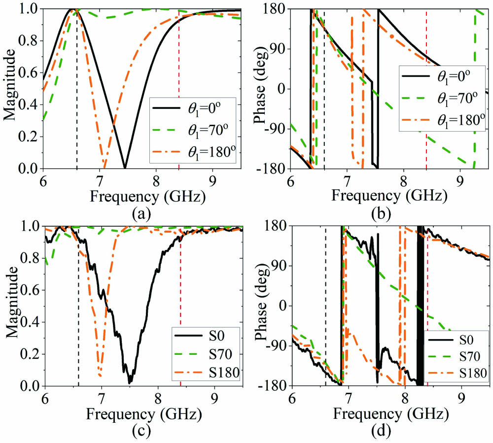
    Fig. 2. Co-polarized reflection coefficient r++ for different values of θ1. (a) Simulated magnitude, (b) simulated phase, (c) measured magnitude, and (d) measured phase. 6.6 GHz and 8.4 GHz are, respectively, highlighted by the vertical black dashed trace and red dashed trace.
    Partial views of the fabricated prototypes. (a) S0, (b) S70, and (c) S180.
    Fig. 3. Partial views of the fabricated prototypes. (a) S0, (b) S70, and (c) S180.
    (a) Magnitude of the co-polarized reflection coefficient r++ of the top and middle C-strips separately. The black and red traces correspond to the middle and top layer strips, respectively. (b) Normalized current distribution of the middle layer strip at 6.6 GHz. (c) Normalized current distribution of the top layer strip at 8.4 GHz.
    Fig. 4. (a) Magnitude of the co-polarized reflection coefficient r++ of the top and middle C-strips separately. The black and red traces correspond to the middle and top layer strips, respectively. (b) Normalized current distribution of the middle layer strip at 6.6 GHz. (c) Normalized current distribution of the top layer strip at 8.4 GHz.
    Relation between rxy and θ1 at 6.6 GHz and 8.4 GHz. (a) Magnitude, (b) phase.
    Fig. 5. Relation between rxy and θ1 at 6.6 GHz and 8.4 GHz. (a) Magnitude, (b) phase.
    Relations between r++ and θ1 at 6.6 GHz and 8.4 GHz. (a) Magnitude, (b) phase.
    Fig. 6. Relations between r++ and θ1 at 6.6 GHz and 8.4 GHz. (a) Magnitude, (b) phase.
    Schematics of the operating principles of (a) MTS1 and (d) MTS2. Phase profiles of MTS1 at (b) 6.6 GHz and (c) 8.4 GHz. Phase profiles of MTS2 at (e) 6.6 GHz and (f) 8.4 GHz.
    Fig. 7. Schematics of the operating principles of (a) MTS1 and (d) MTS2. Phase profiles of MTS1 at (b) 6.6 GHz and (c) 8.4 GHz. Phase profiles of MTS2 at (e) 6.6 GHz and (f) 8.4 GHz.
    Partial view of the fabricated MTSs. (a) MTS1 and (b) MTS2. (c) Photograph of measurement setup showing the MTS illuminated by a horn antenna. (d) Schematic illustration of the far-field measurement setup in a microwave anechoic chamber.
    Fig. 8. Partial view of the fabricated MTSs. (a) MTS1 and (b) MTS2. (c) Photograph of measurement setup showing the MTS illuminated by a horn antenna. (d) Schematic illustration of the far-field measurement setup in a microwave anechoic chamber.
    Normalized magnitude of RCP electric field in the far-field region plotted versus detection angle and frequency of MTS1. (a) Simulated and (c) measured results in the xoz plane. (b) Simulated and (d) measured results in the yoz plane.
    Fig. 9. Normalized magnitude of RCP electric field in the far-field region plotted versus detection angle and frequency of MTS1. (a) Simulated and (c) measured results in the xoz plane. (b) Simulated and (d) measured results in the yoz plane.
    Normalized magnitude of RCP electric field in the far-field region plotted versus detection angle and frequency of MTS2 in the xoz plane. (a) Simulated and (b) measured results.
    Fig. 10. Normalized magnitude of RCP electric field in the far-field region plotted versus detection angle and frequency of MTS2 in the xoz plane. (a) Simulated and (b) measured results.
    Simulated and measured RCP reflection efficiencies of MTS1 and MTS2.
    Fig. 11. Simulated and measured RCP reflection efficiencies of MTS1 and MTS2.
    Jinxing Li, Yueyi Yuan, Qun Wu, Shah Nawaz Burokur, Kuang Zhang. Dual-band independent phase control based on high efficiency metasurface [Invited][J]. Chinese Optics Letters, 2021, 19(10): 100501
    Download Citation