Abstract
This paper reports the experimental realization of efficiently sorting vector beams by polarization topological charge (PTC). The PTC of a vector beam can be defined as the repetition number of polarization state change along the azimuthal axis, while its sign stands for the rotating direction of the polarization. Here, a couple of liquid crystal Pancharatnam–Berry optical elements (PBOEs) have been used to introduce conjugated spatial phase modulations for two orthogonal circular polarization states. Applying these PBOEs in a 4-f optical system, our experiments show the setup can work for PTC sorting with a separation efficiency of more than 58%. This work provides an effective way to decode information from different PTCs, which may be interesting in many fields, especially in optical communication.1. INTRODUCTION
In the recent decades, orbital angular momentum (OAM) of optical vortex beams has drawn much attention. As one of the promising applications of OAM, some research has shown that OAM-based multiplexing and demultiplexing technologies can drastically enhance the capacity of optical communications systems due to the orthogonality of OAM eigenstates [1,2]. So detecting optical vortex (OV) beams becomes critical in spite of challenges. Since the first demonstration of the ability to sort OAM for a single photon by using a cascading series of Mach–Zehnder interferometers [3], many efforts have been devoted to decoding OAM information for developing vortex optical communication [4–8]. A highly efficient design for OAM sorting is noticeable. It can be implemented by optical geometric conversion and optical phase correction to convert a helical phase into a linear phase gradient [9,10]. Based on this idea, Walsh [11] has theoretically improved the OAM sorting system with Pancharatnam–Berry phase optical elements (PBOEs) to simultaneously sort the OAM and spin angular momentum (SAM) compositions of optical beams.
A vector beam is a beam with a space-dependent polarization distribution or a pure laser mode with an additional spatial polarization modulation characterized by polarization topological charge (PTC) [12–16]. Recently, vector beams have also been deemed to be available for improving the capacity of optical communication systems because the vector beam modes with different PTCs are also orthogonal to each other [17–19]. In addition, the vector modes are the eigenmodes in an optical fiber, which have the robustness of propagation in fiber [20–22]. Nevertheless, so far, we have not found any reports on experimental realization to efficiently sort vector light by PTC, like the efficient OAM sorting system.
As we know, a vector beam with a PTC value of can be decomposed into two vortex components with two opposite topological charge values , corresponding to two orthogonal polarization states [17]. Apparently, if a vector beam passes into an OAM sorting system, the beam will be split into two spots due to their opposite topological charges, which means the OAM sorting system [10,23] fails to sort vector beams by PTC. Here we experimentally demonstrate an efficient system to sort vector beams by PTC. In the setup, we use a pair of PBOEs in a 4-f optical imaging system for optical geometric transformation and optical phase correction. The PBOEs are created from liquid crystals (LCs). Our setup can convert the two opposite OAM vortexes of one vector beam into the same direction plane waves and guide them to the same location representing the PTC of the incident vector beam, so it is able to implement PTC sorting. Our experimental results verify that the setup has a separation efficiency of more than 58%.
Sign up for Photonics Research TOC. Get the latest issue of Photonics Research delivered right to you!Sign up now
2. DESIGN PRINCIPLE OF LC-BASED PBOEs
Here the vector beam mode is a mode with localized linear polarization, and a vector beam mode with an integral PTC of can be expressed as [17,18] where represents the initial polarization angle, while is the azimuthal angle in polar coordinates. Equation (1) means that a vector beam with an integral PTC of can be decomposed into two OAM vortexes that have two opposite topological charges of and corresponding to orthogonal polarization states: the left-handed and right-handed circular polarizations ( and ). If we have some optical phase elements to convert the conjugated helical phases with and into same linear phase gradient, we can realize PTC sorting. Interestingly, we find the PBOE can work well for the conversion. PBOE is essentially a piece of half-wave plate with spatially dependent optical axis distribution . The Jones matrix can be written as [24]
For the incident fields with left- and right-handed circularly polarized components and , they can be expressed with the linear polarization components and by
Consequently, for an incident vortex beam with two circular polarization components and , the output from the PBOEs can be calculated by
Accordingly, PBOE will introduce conjugated spatial phase modulation and to and , while changing the polarization (for the input the output is ). For convenience of discussion, we use the initial polarization to name the polarization component in the following discussion.
Due to the great optical anisotropy and the controllable continuously variant optical axis distribution, we choose LC to realize PBOE. LC is a birefringent material, and the refractive index difference will result in phase retardation [25]. Obviously, an LC can work as a half-wave plate by appropriately choosing the refractive indices and the cell gap or applied voltages of LCs.
Figure 1(a) shows the proposed PTC sorting device, a 4-f imaging system with a pair of LC-based PBOEs as the optical geometric transverter (OGT) and optical phase corrector (OPC). We design the PBOEs so that the of Eq. (4) becomes for OGT and for OPC. Here, is the focal length of the used lenses. The positive parameters and in Eqs. (5) and (6) scale and translate the transformed beam in the Fourier plane of the system.
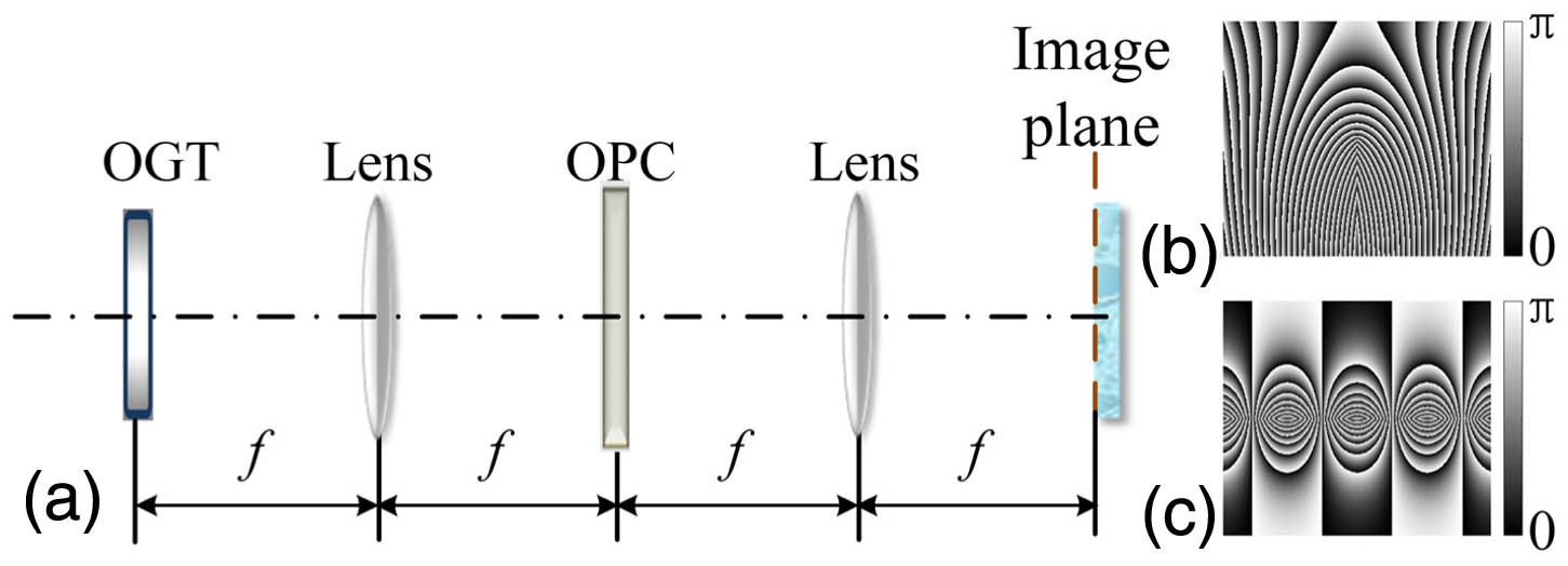
Figure 1.(a) PTC sorting setup, (b) the angle function of optical geometric transverter (OGT), and (c) of optical phase corrector (OPC).
As mentioned above, both the OGT and OPC were designed based on LCs and manufactured by photo-alignment technology [25,26]. A polarization-sensitive alignment agent, together with a dynamic microlithography system, is used to control the orientation of the optical axis of the LCs. Setting the external voltage at 2.5 V can effectively realize our target function at the wavelength of 632.8 nm (operating wavelength of He–Ne laser). Figures 1(b) and 1(c) show the space-variant orientations of OGT and OPC. Each of the manufactured PBOEs has its inserted loss of about 14%, which originates mainly from their glass substrates, and thus can be improved greatly with anti-reflection coating on the substrate surfaces. The total transmittance of our system is about 70%.
The phase modulation by OGT for , , is conjugated with that for , . is the same as the phase profile of the transforming element for OAM sorting [9]. Compared to , can be considered as the parameter is replaced by . Figure 2 numerically simulates the evolution of the spatial intensity distribution of an incident vector beam with a PTC of in our PTC sorting system. Here, the red and green intensity distributions are used to represent the spatial intensity of the and . The initial intensity profile results from the mixture of a red donut and a green donut, and thereby exhibits yellow. In order to present the mapping relationships during the transformation, we use red and green rings with an arrow at the bottom of Fig. 2 to represent the intensity distribution of the two OAM vortexes, while the arrow direction represents the direction of the helical phase gradient. After passing the OGT, the red ring and green ring break from below, having the geometric optical transformations, but deformations are in the different processes due to the conjugated phase modulation. Finally, both rings are straightened at the OPC plane. and spread symmetrically with regard to the center horizontal line (white dotted line in Fig. 2), and we can note that the directions of the two arrows are same. It means that if the phase of and can be corrected to plane waves as the OAM sorting system, the two opposite OAM vortexes will transform into the same-direction plane waves. If each straightened beam does not cross the center horizontal line, then we can have a phase correction function for below the center horizontal line (the same phase correction function as in Ref. [9]; there is a factor of due to the polarization change by OGT), and phase correction function for above the center horizontal line (compared with the former, it can be considered as the parameter is replaced by ). Then we can get the fast axis angles of OPC as Eq. (6). It is noticeable that, in the right side of Eq. (6), is used instead of the corresponding in the phase correction function in the OAM sorting system [9]. And the incident light radius is required to be less than so that the straightened beam will not be across the center horizontal line. After going through the OPC, the and will be phase corrected to be the plane waves with an identical propagation direction. Eventually, after the second lens, the and of the vector beam will overlap entirely with each other on the image plane. Consequently, our system can guide its incident vector beam onto the image plane by PTC.

Figure 2.Simulation of the optical geometric transformation of vector beams with . OGT is at , the first lens is at and OPC is at .
3. EXPERIMENTS AND DISCUSSIONS
In our setup, the focal length of the lenses is chosen to be 1000 mm. The used light source is a continuous-wave (CW) He–Ne laser operating at 632.8 nm with a beam radius of 2 mm on the OGT. The parameters and are set at 1 mm and 5 mm. The effective sizes of our PBOEs are limited to for both the OGT and OPC. In order to check the manufacture qualities of our PBOE for the OGT, we have recorded the intensity profiles with an incident linearly polarized beam () by our charge-coupled device (CCD) camera at a propagation distance from the first lens to OPC: , 750, and 1000 mm, as shown in Figs. 3(a)–3(c). For comparison, we also present the corresponding numerical simulations in Figs. 3(d)–3(f). As our prediction, after going through the OGT, the intensity profiles consist of two parts, which correspond to two orthogonal polarization components. The two parts deviate from each other and diffract in different directions due to experiencing different geometric optical transformations from the OGT. However, after the phase modulation from the first lens, the two beam profiles become straightened and distribute symmetrically along the vertical direction at the OPC plane () as discussed above. From Fig. 3, we can see there exists good accordance between simulations and experimental detections, and we think the differences between the experimental records and theoretical simulations originate mainly from the imperfect manufactures of the LC PBOE, which can induce additional optical diffraction. Similar checks are also carried out for the OPC, which also shows the experimental detections agree well with theoretical simulations.
Figure 3.Intensity profiles at a distance from the first lens to OPC: , 750, 1000 mm. (a)–(c) are experimental records by CCD camera, while (d)–(f) are simulation results.
In our experiments, the incident vector beams with different PTCs are obtained by using different -plates [27,28] with linearly polarized beams, each of which is also an LCs-based plate with a matched electrical field. Figure 4(a) presents an example intensity profile of an incident vector beam with , and their horizontal and vertical polarization components are separated by a Wollaston polarizer and recorded as shown in Figs. 4(b) and 4(c). When a vector beam passes through our setup as shown in Fig. 1(a), it is finally focused into one spot at the image plane. By using different -plates, we have recorded different beam spots as shown in Fig. 4(d), where the beam spots with different PTC values of , 1, 0, , and , are well separated at the image plane. Yellow, red, white, green, and violet correspond to , 1, 0, , and , respectively. One can see that the system can guide the beams by different PTCs to different positions at the image plane. If the applied voltages are mismatched, for a linearly polarized incident beam, the output from the -plate will include a vector beam with a target PTC of and some residue of the incident with . Here we get the incident beam consisting of two components with and by using a -plate with its target but operating at a mismatched voltage. Consequently, there are two separated elongated spots at the image plane as shown in Fig. 4(e).
Figure 4.(a) Intensity profile of incident vector beam with , (b) the horizontal and (c) the vertical polarization components, and the intensity distributions at image plane for the incident beam with PTC values of (d) , , 0, 1, and 2, and (e) and .
Because our system sorts vector beams with PTC along the direction, we apply an integration to each recorded intensity of the elongated spots in Fig. 4(d) along the direction to appraise the PTC sorting. Figure 5(a) exhibits the normalized -directional integral intensity distribution of the vector fields along the direction with different PTC values, where is the distance between central positions of the spots with adjacent topological charges, while represents the transverse spatial position. Figure 5(a) implies that some of the light in a state leaks into its neighboring regions, i.e., some crosstalk occurs between different states.
Figure 5.(a) –directional integral intensity distribution of the vector fields along the direction with the PTC values of , , 0, 1, and 2 at the image plane. (b) Experimental intensity distribution via different PTC values from to 2 over whole detection regions.
In order to assess the crosstalk, we calculate the separation efficiency, which was defined by Mirhosseini et al. [29] but use PTC instead of OAM to evaluate the probability of PTC sorting. Figure 5(b) shows the total energy distribution detected by the detector, where the ordinate value stands for the different detector and the abscissa does for the polarization topological charge. From our records, the calculated separation efficiencies with , , 0, 1, and 2 were 62.6%, 61.7%, 62%, 60.2%, and 58%, respectively. The corresponding theoretical simulations are 78.8%, 79.4%, 76.8%, 79.4%, and 78.8%. Obviously, the simulation data are higher than our experimental results. We guess the degradation of the experimental data from the theoretical prediction may mainly result from the imperfect manufactures of our PBOEs, which can lead to imperfect optical phase transformation and phase correction.
4. CONCLUSIONS
Summarily, this paper realizes experimentally the efficient vector beams sorting by PTCs with a couple of liquid crystal PBOEs in a 4-f optical system. The liquid crystal PBOEs have been designed and manufactured to introduce conjugated spatial phase modulations for two orthogonal circular polarization states. These PBOEs help for conversion of the two opposite helical phases of the two orthogonal polarization states into a same linear phase gradient. And the two OAM vortexes of one vector beam are focused on the same location representing the PTC of the incident vector beam. According to our experiments, the setup can work as a PTC sorting system with a separation efficiency more than 58%. The efficiencies are lower than theoretical predictions. We think it shall mainly be from the imperfect manufactures of our PBOEs, which can result in imperfect optical transformation and phase correction. This work provides an effective way to decode information from different PTCs, which may be interesting in many fields, e.g., in optical communication.
References
[1] A. M. Yao, M. J. Padgett. Orbital angular momentum: origins, behavior and applications. Adv. Opt. Photon., 3, 161-204(2011).
[2] A. E. Willner, H. Huang, Y. Yan, Y. Ren, N. Ahmed, G. Xie, C. Bao, L. Li, Y. Cao, Z. Zhao, J. Wang, M. P. J. Lavery, M. Tur, S. Ramachandran, A. F. Molisch, N. Ashrafi, S. Ashrafi. Optical communications using orbital angular momentum beams. Adv. Opt. Photon., 7, 66-106(2015).
[3] J. Leach, M. J. Padgett, S. M. Barnett, S. Franke-Arnold, J. Courtial. Measuring the orbital angular momentum of a single photon. Phys. Rev. Lett., 88, 257901(2002).
[4] J. Wang, J. Yang, I. M. Fazal, N. Ahmed, Y. Yan, H. Huang, Y. Ren, Y. Yue, S. Dolinar, M. Tur, A. E. Willner. Terabit free-space data transmission employing orbital angular momentum multiplexing. Nat. Photonics, 6, 488-496(2012).
[5] H. Huang, G. Milione, M. P. J. Lavery, G. Xie, Y. Ren, Y. Cao, N. Ahmed, A. N. Thien, D. A. Nolan, M. Li, M. Tur, R. R. Alfano, A. E. Willner. Mode division multiplexing using an orbital angular momentum mode sorter and MIMO-DSP over a graded-index few-mode optical fibre. Sci. Rep., 5, 14931(2015).
[6] J. Wang, J. Yang, I. M. Fazal, N. Ahmed, Y. Yan, B. Shamee, A. E. Willner, K. Birnbaum, J. Choi, B. Erkmen, S. Dolinar, M. Tur. 25.6-bit/s/Hz spectral efficiency using 16-QAM signals over pol-muxed multiple orbital-angular-momentum modes. IEEE Photonics Conference, 58, 587-588(2011).
[7] C. Li, S. Zhao. Efficient separating orbital angular momentum mode with radial varying phase. Photon. Res., 5, 267-270(2017).
[8] T. Lei, M. Zhang, Y. Li, P. Jia, G. N. Liu, X. Xu, Z. Li, C. Min, J. Lin, C. Yu, H. Niu, X. Yuan. Massive individual orbital angular momentum channels for multiplexing enabled by Dammann gratings. Light Sci. Appl., 4, e257(2015).
[9] G. C. G. Berkhout, M. P. J. Lavery, J. Courtial, M. W. Beijersbergen, M. J. Padgett. Efficient sorting of orbital angular momentum states of light. Phys. Rev. Lett., 105, 153601(2010).
[10] M. P. J. Lavery, D. J. Robertson, G. C. G. Berkhout, G. D. Love, M. J. Padgett, J. Courtial. Refractive elements for the measurement of the orbital angular momentum of a single photon. Opt. Express, 20, 2110-2115(2012).
[11] G. F. Walsh. Pancharatnam-Berry optical element sorter of full angular momentum eigenstate. Opt. Express, 24, 6689-6704(2016).
[12] C. Maurer, A. Jesacher, S. Fuerhapter, S. Bernet, M. Ritsch-Marte. Tailoring of arbitrary optical vector beams. New J. Phys., 9, 78(2007).
[13] Q. Zhan. Cylindrical vector beams: from mathematical concepts to applications. Adv. Opt. Photon., 1, 1-57(2009).
[14] G. Milione, H. I. Stzul, D. A. Nolan, R. R. Alfano. Higher-order Poincaré sphere, stokes parameters, and the angular momentum of light. Phys. Rev. Lett., 107, 053601(2011).
[15] S. Fu, Y. Zhai, T. Wang, C. Yin, C. Gao. Tailoring arbitrary hybrid Poincaré beams through a single hologram. Appl. Phys. Lett., 111, 211101(2017).
[16] S. Fu, C. Gao, Y. Shi, K. Dai, L. Zhong, S. Zhang. Generating polarization vortices by using helical beams and a Twyman Green interferometer. Opt. Lett., 40, 1775-1778(2015).
[17] Z. Xie, T. Lei, X. Weng, L. Du, S. Gao, Y. Yuan, S. Feng, Y. Zhang, X. Yuan. A miniaturized polymer grating for topological order detection of cylindrical vector beams. IEEE Photon. Technol. Lett., 28, 2799-2802(2016).
[18] G. Milione, A. N. Thien, J. Leach, D. A. Nolan, R. R. Alfano. Using the nonseparability of vector beams to encode information for optical communication. Opt. Lett., 40, 4887-4890(2015).
[19] G. Milione, M. P. J. Lavery, H. Huang, Y. Ren, G. Xie, A. N. Thien, E. Karimi, L. Marrucci, D. A. Nolan, R. R. Alfano, A. E. Willner. 4 × 20 Gbit/s mode division multiplexing over free space using vector modes and a q-plate mode (de)multiplexer. Opt. Lett., 40, 1980-1983(2015).
[20] B. Ndagano, R. Bruening, M. McLaren, M. Duparre, A. Forbes. Fiber propagation of vector modes. Opt. Express, 23, 17330-17336(2015).
[21] S. Ramachandran, P. Kristensen, M. F. Yan. Generation and propagation of radially polarized beams in optical fibers. Opt. Lett., 34, 2525-2527(2009).
[22] W. Qiao, T. Lei, Z. Wu, S. Gao, Z. Li, X. Yuan. Approach to multiplexing fiber communication with cylindrical vector beams. Opt. Lett., 42, 2579-2582(2017).
[23] M. Lavery, D. Robertson, M. Malik, B. Rodenburg, J. Courtial, R. W. Boyd, M. J. Padgett. The efficient sorting of light’s orbital angular momentum for optical communications. Proc. SPIE, 8542, 85421R(2012).
[24] L. Marrucci, C. Manzo, D. Paparo. Pancharatnam-Berry phase optical elements for wavefront shaping in the visible domain: switchable helical modes generation. Appl. Phys. Lett., 88, 221102(2006).
[25] P. Chen, S. Ge, W. Duan, B. Wei, G. Cui, W. Hu, Y. Lu. Digitalized geometric phases for parallel optical spin and orbital angular momentum encoding. ACS Photon., 4, 1333-1338(2017).
[26] W. Ji, C. Lee, P. Chen, W. Hu, Y. Ming, L. Zhang, T. Lin, V. Chigrinov, Y. Lu. Meta-q-plate for complex beam shaping. Sci. Rep., 6, 25528(2016).
[27] P. Chen, W. Ji, B. Wei, W. Hu, V. Chigrinov, Y. Lu. Generation of arbitrary vector beams with liquid crystal polarization converters and vector-photoaligned q-plates. Appl. Phys. Lett., 107, 241102(2015).
[28] J. A. Davis, N. Hashimoto, M. Kurihara, E. Hurtado, M. Pierce, M. M. Sanchez-Lopez, K. Badham, I. Moreno. Analysis of a segmented q-plate tunable retarder for the generation of first-order vector beams. Appl. Opt., 54, 9583-9590(2015).
[29] M. Mirhosseini, M. Malik, Z. Shi, R. W. Boyd. Efficient separation of the orbital angular momentum eigenstates of light. Nat. Commun., 4, 2781(2013).


