• High Power Laser Science and Engineering
  • Vol. 11, Issue 2, 02000e29 (2023)
Zilin Zhao1, Daping Luo1, Yang Liu1、*, Zejiang Deng1, Lian Zhou1, Gehui Xie1, Chenglin Gu1, Yanzhao Yang2, Bin Wu2, and Wenxue Li1、*
Author Affiliations
  • 1State Key Laboratory of Precision Spectroscopy, East China Normal University, Shanghai, China
  • 2The 41st Institute of China Electronics Technology Group Corporation, Qingdao, China
  • show less
    DOI: 10.1017/hpl.2023.21 Cite this Article Set citation alerts
    Zilin Zhao, Daping Luo, Yang Liu, Zejiang Deng, Lian Zhou, Gehui Xie, Chenglin Gu, Yanzhao Yang, Bin Wu, Wenxue Li. Tunable compact asynchronous optical sampling system using Er-doped fiber laser[J]. High Power Laser Science and Engineering, 2023, 11(2): 02000e29 Copy Citation Text show less
    (a) Setup of the ASOPS system. CIR+WDM, 980/1550 nm wavelength-division multiplexer fiber circulator; EDF, Er-doped fiber; SESAM, semiconductor saturable absorption mirror; PZT, piezoelectric transducer; FDL, electrically controlled fiber delay line; IWDM, wavelength-division multiplexer with isolator; PD, fiber-coupled photodiode; Raman, polarization-maintaining Raman fiber; PS, power splitter; PLO, phase-locked oscillator; DDS, direct-digital synthesis component; BP, electronic band-pass filter; AMP, amplifier; M1 and M2, electronic mixers; PLL1 and PPL2, phase-locked loops; fM, master repetition rate; fS, slave repetition rate; Δfset, desired offset frequency. The formulas in blue give the corresponding frequencies inside the error-signal unit branches. The straight and dashed lines correspond to the optical beams and electronic connections, respectively. (b) Internal structure diagram of the ASOPS system. The master and slave lasers were enclosed in two closed copper boxes, respectively. (c) Integrated ASOPS system prototype.
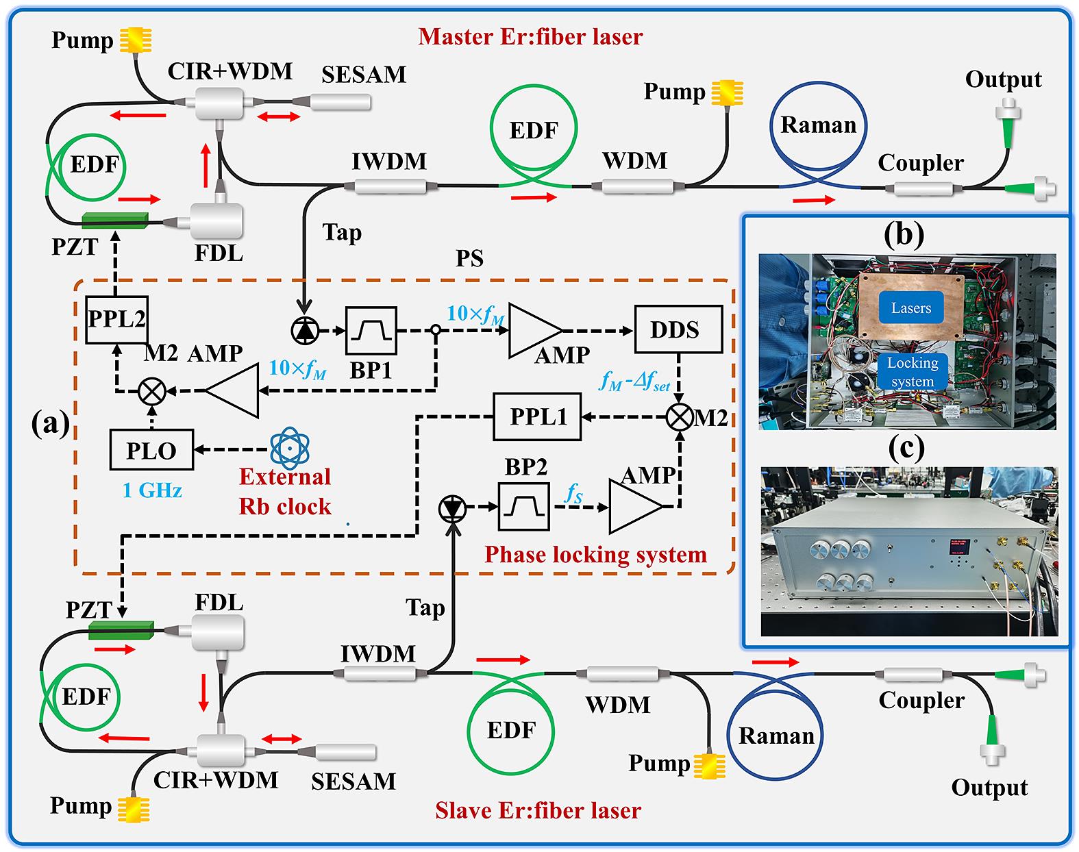
    Fig. 1. (a) Setup of the ASOPS system. CIR+WDM, 980/1550 nm wavelength-division multiplexer fiber circulator; EDF, Er-doped fiber; SESAM, semiconductor saturable absorption mirror; PZT, piezoelectric transducer; FDL, electrically controlled fiber delay line; IWDM, wavelength-division multiplexer with isolator; PD, fiber-coupled photodiode; Raman, polarization-maintaining Raman fiber; PS, power splitter; PLO, phase-locked oscillator; DDS, direct-digital synthesis component; BP, electronic band-pass filter; AMP, amplifier; M1 and M2, electronic mixers; PLL1 and PPL2, phase-locked loops; fM, master repetition rate; fS, slave repetition rate; Δfset, desired offset frequency. The formulas in blue give the corresponding frequencies inside the error-signal unit branches. The straight and dashed lines correspond to the optical beams and electronic connections, respectively. (b) Internal structure diagram of the ASOPS system. The master and slave lasers were enclosed in two closed copper boxes, respectively. (c) Integrated ASOPS system prototype.
    Spectra of the (a) master and (b) slave lasers centered at 1565 nm. Autocorrelation traces of the (c) master and (d) slave lasers. The dashed lines represent the Gaussian curves fitted to the autocorrelation traces.
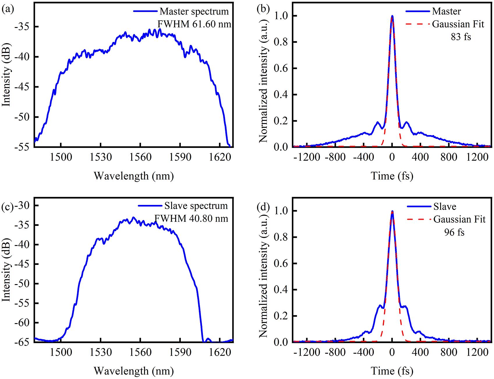
    Fig. 2. Spectra of the (a) master and (b) slave lasers centered at 1565 nm. Autocorrelation traces of the (c) master and (d) slave lasers. The dashed lines represent the Gaussian curves fitted to the autocorrelation traces.
    Recorded repetition rates of (a) master laser fM, (d) slave laser fS and (g) Δf. Counts of (b) fM, (e) fS and (h) Δf. Overlapping Allan deviations of the recorded (c) fM, (f) fS and (i) Δf. (j) Phase noise measurements of the locking master and slave lasers.
    Fig. 3. Recorded repetition rates of (a) master laser fM, (d) slave laser fS and (g) Δf. Counts of (b) fM, (e) fS and (h) Δf. Overlapping Allan deviations of the recorded (c) fM, (f) fS and (i) Δf. (j) Phase noise measurements of the locking master and slave lasers.
    Time-domain interference signals of the ASOPS system with Δf of (a) 100 Hz, (b) 200 Hz and (c) 300 Hz. (d) Repetition rate of the slave laser locked at different Δf from 1 Hz to 1 MHz. (e) Tunable repetition rate of the slave laser with FDL modulations.
    Fig. 4. Time-domain interference signals of the ASOPS system with Δf of (a) 100 Hz, (b) 200 Hz and (c) 300 Hz. (d) Repetition rate of the slave laser locked at different Δf from 1 Hz to 1 MHz. (e) Tunable repetition rate of the slave laser with FDL modulations.
    (a) Experimental setup of the TDS spectrometer. (b) Temporal waveform and (c) power spectrum of the pulsed THz radiation obtained at a 50-sweep measurement.
    Fig. 5. (a) Experimental setup of the TDS spectrometer. (b) Temporal waveform and (c) power spectrum of the pulsed THz radiation obtained at a 50-sweep measurement.
    Zilin Zhao, Daping Luo, Yang Liu, Zejiang Deng, Lian Zhou, Gehui Xie, Chenglin Gu, Yanzhao Yang, Bin Wu, Wenxue Li. Tunable compact asynchronous optical sampling system using Er-doped fiber laser[J]. High Power Laser Science and Engineering, 2023, 11(2): 02000e29
    Download Citation