
Zhenlan WANG, Junli GOU, Shihao XU, Zheng WANG, Jianqiang SHAN, Simao GUO, Bin TANG. Heat pipe failure accident analysis of a new type of megawatt heat pipe reactor[J]. NUCLEAR TECHNIQUES, 2022, 45(11): 110604
- NUCLEAR TECHNIQUES
- Vol. 45, Issue 11, 110604 (2022)
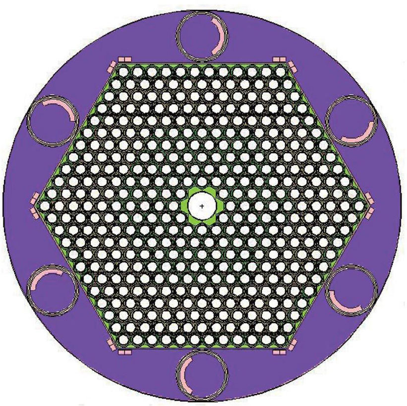
Fig. 1. Diagram of a new type heat pipe reactor core
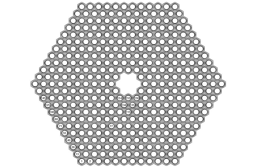
Fig. 2. Component numbering
Fig. 3. Structure diagram of single heat pipe-fuel assembly
Fig. 4. Diagram of core cavity
Fig. 5. Equivalent network diagram of radiation heat transfer in the core cavity
Fig. 6. Schematic of mesh
Fig. 7. Verification of grid independence
Fig. 8. Temperature field contour under steady condition (a) At the axial midpoint of the evaporation section, (b) Core axial section
Fig. 9. Axial temperature distribution of No.155 component
Fig. 10. Transient variation of single heat pipe failure (a) Transient variation of reactivity and normalized power, (b) Transient variation of peak temperature
Fig. 11. Average normalized output power of each circle of heat pipes and normalized total input and output power (a) Case 1, (b) Case 2, (c) Case 3
Fig. 12. Output power of failed heat pipe and surrounding heat pipes (a) Case 1, (b) Case 2, (c) Case 3
Fig. 13. Axial temperature distribution of heat pipe failure (a) No.155 heat pipe failure, (b) No.156 heat pipe failure, (c) No.134 heat pipe failure
Fig. 14. Transient variation of three heat pipe failure (a) Transient variation of reactivity and normalized power, (b) Transient variation of peak temperature
Fig. 15. Transient variation of peak temperature in condition of four heat pipe failure
Fig. 16. Transient variation of parameters in case 3 and case 7 (a) Transient variation of reactivity and normalized power, (b) Transient variation of peak temperature and core average temperature
Fig. 17. Temperature field contour at the axial midpoint of the evaporation section (z=0.275 m) in case 7
|
Table 1. Single heat pipe-fuel assembly parameters
|
Table 2. Neutron dynamic parameters of core and power distribution
|
Table 3. Peak temperature of single heat pipe failure
| ||||||||||||||||||||||||||||||||||||||||||
Table 4. Comparison of the peak temperature of three heat pipe failure under different boundary conditions
|
Table 5. Comparison of the peak temperature of case 3 and case 7


Set citation alerts for the article
Please enter your email address

© Copyright 2018-2021 | Chinese Laser Press. All Rights Reserved 沪ICP备15018463号-20