Qiuzhi Qu, Bin Wang, Desheng Lü, Jianbo Zhao, Meifeng Ye, Wei Ren, Jingfeng Xiang, Liang Liu, "Integrated design of a compact magneto-optical trap for space applications," Chin. Opt. Lett. 13, 061405 (2015)
Copy Citation Text
In this Letter, we describe an optical assembly that is designed for the engineering application of the atomic laser cooling techniques. Using a folded optical path scheme, we have built a miniaturized, compact magneto-optical trap (CMOT) for an atomic fountain clock. Compared with the conventional magneto-optical traps used in other clocks, our system is more robust, more compact, more stable, and saves about 60% laser power. This optical setup has operated for about a year in our fountain system, passed the thermal cycle tests and the mechanical vibration and shock tests, and maintained a high performance without a need for realignment.
In recent years, atomic laser cooling techniques combined with a microgravity environment have allowed for the development of atom clocks with unprecedented performances[1–6]. This means the laser cooling devices can be placed outside of the science laboratories on the Earth and thus, the first steps can be taken into the field of space engineering, such as building a cold atomic fountain clock to serve as a space frequency standard.
Typically, a cold atom clock has two main subsystems in physics[7–9]: an ultra-high vacuum (UHV) atomic tube in which atoms interact with microwaves and laser beams, and an optical system providing near-infrared laser sources for trapping, cooling, launching, and detecting the atoms in the detection zone. The laser sources have strict requirements in spectral purity, spectral stability, accurate frequency tuning capability, and power stability, and the laser beams have been set to ensure there are tight constraints on the envelope, direction, and position. To meet the space engineering challenge, a cold atom clock intended for use in space demands much a higher performance to cope with the extremely severe carrying constraints in terms of weight and size, reliability, stability, safety, behavior under harsh environmental constraints, and so on. A number of specific mechanisms and optical assemblies must be developed for robustness and compactness. In this work, we describe a particular compact magneto-optical trap (CMOT) assembly that has been mounted on our atomic fountain clock for a space experiment, and we present the initial scientific test results.
To achieve the required scientific targets of an atomic fountain clock for space, over atoms need to be trapped and cooled to a temperature of several micro-kelvins, then launched precisely along the UHV central axis by the so-called moving molasses technique. One of the most efficient methods of cooling atoms involves using a magneto-optical trap (MOT). A standard method to construct a MOT involves injecting three pairs of counter-propagating cooling laser beams into the capture zone of the UHV tube through optical fibers to form an optical trap, then adding two magnetic coils beside the capture zone to produce an heterogeneous magnetic field. Finally, the position of the coils must be calibrated to overlap the zero point of magnetic field within the center of the optical trap.
Sign up for Chinese Optics Letters TOC. Get the latest issue of Chinese Optics Letters delivered right to you!Sign up now
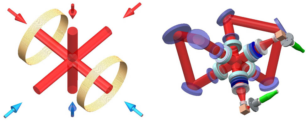
Figure 1 (left) shows the schematic of a conventional MOT, which is composed of the following key components: layers of magnetic shields that block the atoms from being interfered with by outside magnetic fields, an UHV atomic tube with some quartz glass windows in the capture zone, six optical fibers that emit the corresponding laser sources with an ultra-narrow line width and accurate frequency into the fiber ports, at least six large-diameter laser beams propagating into the trap center along three-dimensional orthogonal directions, a laser polarization control system that properly polarizes each incident beam, and a pair of anti-Helmholtz magnetic coils.
Figure 1.A conventional MOT (left) compared with a compact folded optical path style trap (right).
Since magnetic shields made of heavy perm-alloy metal containing iron and nickel (45%–80%) are one of the main components that add to the clock’s weight, their diameters must as small as possible to reduce the total weight of the clock. Hence, the inside optical elements and mechanisms have to be designed to be a smaller size. However, the requirement of six large-diameter laser beams in a conventional MOT means that there must be six optical fibers and six groups of collimating and expanding optical systems. It is difficult to set up all of the opto-mechanical components and fibers in a small magnetic shield tube, considering the necessary optical path length and the minimum turning radius of the fiber pigtails.
We have achieved a solution to these problems by using the CMOT shown in Fig. 1 (right), which is based on the previous work of the folded optical path style atomic fountain clock in our laboratory[10]. We used only two input laser beams instead of six, accounting for the difference by creating multiple reflections with a group of well-arranged mirrors. Then, we combined the optical collimating and expanding lens and the laser polarization control elements along the path of beams, and upgraded the opto-mechanical design to minimize the stress within the components caused by temperature changes and mechanical vibrations. Finally, we wound the anti-Helmholtz magnetic coils on one path of the six beams. This structure then completely overlaps the optical trap center with the zero point of magnetic field.
The CMOT construction is shown in Fig. 2. To be fit for the launch of a rocket and to be able to adapt to the tremendous mechanical and thermal vibrations at the same time, the stability of the CMOT is important. It must be very resistant to both thermal expansion and mechanical vibration.
Figure 2.Set of the CMOT mechanism. The up and down flanges are separately connected with ion pumps and an atomic clock chamber .
First, we select titanium as a suitable material with which to build the UHV atomic tube. Titanium is strong and easily machinable with a small thermal expansion coefficient, allowing for a rigid construction to help with mechanical stability. Second, we combine the optical components and mechanisms with several modules, such as the input laser beam transform module, the laser beam reflecting module, the magnetic coils module, and the fluorescent light-detecting module. In every module, a group of elementary optical components, such as fiber ports, beam splitters, lenses, wave plates and mirrors, are fixed on an exquisite mechanical mount. Each module is pre-aligned before being integrated in the atomic cavity. .
The capture zone of the atomic tube is a hollow cube whose eight corners have been cut off along the lines connected to the midpoints of the edges. Two input laser modules and four laser reflecting modules are mounted on the six square sides of the polyhedral. Two transit mirror modules, a Rb source, and a fluorescent light detector are mounted on the corner sides. Using this compact design, we can then integrate all of the required components in a small size, shorten the optical path lengths of the lasers, and then improve the stability of the system.
A further factor affecting the stability of the system is the stress within the optical materials and the machinated mounted surfaces caused by differential radial expansion or contraction under temperature changes. In order to hold a single lens in a cell, we choose the elastomeric mounting technique[11] that uses an annular ring of a resilient elastomeric material. According to the study of Bayar, if this elastomeric material has a particular thickness , the assembly will, to a first-order approximation, be athermal in the radial direction. This thickness is given by where is the diameter of the lens, and are the coefficients of the thermal expansion of the lens and mount, and is the effective coefficient of the thermal expansion of the elastomer, which in our case, is . We list the thicknesses of the elastomers of our system in Table 1. We calculated every decentration, , of the lenses when they were subjected to radial gravitational loading using the equation where and is the acceleration factor, is the lens weight, is the lens edge thickness, is the elastomer Poisson’s ratio, is the elastomer Young’s modulus, and is the shear modulus of the elastomer.
DG(mm)
Material
αG(°C−1)
αM(°C−1)
te(mm)
δ1(mm)
10
BK7
7.1×10⁻⁶
23.6×10⁻⁶
1.05
4.7×10⁻⁵
20
BK7
7.1×10⁻⁶
23.6×10⁻⁶
2.10
7.6×10⁻⁵
30
B270
9.4×10⁻⁶
23.6×10⁻⁶
2.72
1.6×10⁻⁴
35
JGS-2
5.5×10⁻⁷
23.6×10⁻⁶
4.41
2.5×10⁻⁴
Table 1. Thicknesses of the Elastomers and Decentration of the Lenses
From the results of the Table 1, we can infer that when the system is under the conditions of shock and vibration, for example, when the loading acceleration factor is up to 250, the maximum decentration of the lenses is about 0.02 mm, which is still quite small. Therefore, the resilient elastomers can restore the lenses to their unstressed locations and orientations when the acceleration force dissipates.
For a three-dimensional MOT, each spatial dimension needs a pair of laser beams with the proper circular polarization[12]. A circularly polarized or laser can be easily transformed from a linearly polarized laser using a wave plate. However, when a circularly polarized light is reflected by a coated glass with high reflectivity, the polarization degree of the light will change from 0 to 1 with a different reflecting angle. For instance, it will be linear when the angle of reflection equals the Brewster angle. This is a main influencing factor on the polarization control of a CMOT system that has so many reflections from the mirrors. According to this reason, we arranged a group of polarization beam splitters and wave plates along the optical path, as shown in Fig. 3. A single-mode optical fiber coming from a laser source injects a diffused light with a numerical aperture of 0.11 into the input laser transform module. After going through a polarization beam splitter, the refracted diffused light has a pure linear polarization. The linear polarization of the collimating light is then changed to circular polarization by a true zero-order wave plate that is insensitive to temperature change. To ensure the that the lasers inside the atomic tube have the proper circular polarizations requires keeping the lasers propagating outside the cavity with linear polarizations, because linear light has a stable characteristic of polarization against reflection and temperature change.
Figure 3.The optical configuration showing one laser path of the CMOT. Another one is counter-propagating along this path completely.
The atoms trapped in the MOT can be observed from one window on a corner surface of the capture zone through an optical imaging module. Using the scattering resonance fluorescence detection method, the atom number of our MOT is obtained by where the total photon scattering rate (integrated over all directions and frequencies) is given by and is output voltage of the detector, is the photoelectric conversion efficiency, is the amplification ratio of the low current amplifier, is the resonance frequency, and is the fractional solid angle of the fluorescent light observation window. In our case, , , and . For example, when is 3.5 V, the atom number is about .
As shown in Fig. 3, using the CMOT scheme, two cooling laser beams can replace the six cooling laser beams used in the standard MOT by being guided into the atomic capture zone three times in a row. Each beam for trapping and cooling is collimated to a beam waist radius of 10 mm at . A maximum intensity of about is obtained at the center of each beam, excluding about a re-pumping laser in one of the two fibers. Since we have developed a long-term, stable optical system to provide the laser sources, the laser power variance of our MOT will be less than in about a year without any adjustment. Using our CMOT optical system, we can trap about Rb atoms in about 1500 ms of loading time for the MOT of our cold atomic clock engineering model intended for use in space. Preliminary studies of the physical system, atomic capture, cooling, and launching have been performed[13–17]. The rubidium atoms were cooled to an ultra-low temperature of about 1.5 μK by the adiabatic cooling technique, then launched by moving molasses, and interacted with a Ramsey cavity to produce the clock signal. The engineering model of the atomic clock for space equipped with a CMOT has been tested in the thermal and vibrational conditions of China’s manned space specifications for months. Figure 4 shows the detected atom number variance in the long-term fountain operation; the mean atom number variance in eight months is about 3.3%. The error bars in Fig. 4 show the atom number variances in the ground tests are mainly affected by the fluctuations in the vacuum degree and the laser power and frequency noises that come from the temperature influences of the environment and the changes in the test conditions. During this period, the whole system has successively passed the engineering thermal cycle test and the mechanical vibration tests, and moved from one place to another 1000 km away, all the while maintaining a high performance without the need for realignment.
Figure 4.The detected atom number variance in a long-term operation.
In conclusion, we construct a miniaturized CMOT of a atomic fountain clock for engineering applications in space. Compared with the conventional MOTs used in other clocks, our system is more robust, more compact, more stable, and saves about 60% laser power. This system is demonstrated to be useful for long-term atomic fountain operation and suitable for a space environment by sustaining the rigorous tests of thermal and mechanical vibration without any irreversible damage.
References
[1] S. Bize, P. Laurent, M. Abgrall, H. Marion, I. Maksimovic, L. Cacciapuoti, J. Grünert, C. Vian, F. Pereira dos Santos, P. Rosenbusch, P. Lemonde, G. Santarelli, P. Wolf, A. Clairon, A. Luiten, M. Tobar, C. Salomon. C. R. Phys., 5, 829(2004).
[2] T. P. Heavner, L. Hollberg, S. R. Jefferts, J. Kitching, W. M. Klipstein, D. M. Meekhof, H. G. Robinson. Trans. Instrum. Meas., 50, 500(2001).
[3] D. B. Sullivan, N. Ashby, E. A. Donley, T. P. Heavner, L. W. Hollberg, S. R. Jefferts, W. M. Klipstein, W. D. Phillips, D. J. Seidel. Adv. Space Res., 36, 107(2005).
Qiuzhi Qu, Bin Wang, Desheng Lü, Jianbo Zhao, Meifeng Ye, Wei Ren, Jingfeng Xiang, Liang Liu, "Integrated design of a compact magneto-optical trap for space applications," Chin. Opt. Lett. 13, 061405 (2015)