• Chinese Optics Letters
  • Vol. 20, Issue 12, 122201 (2022)
Yingying Ren1、*, Zemeng Cui1, Lifei Sun1, Chao Wang1, Hongliang Liu2, and Yangjian Cai1、3、**
Author Affiliations
  • 1Shandong Provincial Engineering and Technical Center of Light Manipulations and Shandong Provincial Key Laboratory of Optics and Photonic Device, School of Physics and Electronics, Shandong Normal University, Jinan 250358, China
  • 2Key Laboratory of Optical Information Science and Technology, Ministry of Education, Institute of Modern Optics, Nankai University, Tianjin 300071, China
  • 3School of Physical Science and Technology, Soochow University, Suzhou 215006, China
  • show less
    DOI: 10.3788/COL202220.122201 Cite this Article Set citation alerts
    Yingying Ren, Zemeng Cui, Lifei Sun, Chao Wang, Hongliang Liu, Yangjian Cai. Laser emission from low-loss cladding waveguides in Pr:YLF by femtosecond laser helical inscription[J]. Chinese Optics Letters, 2022, 20(12): 122201 Copy Citation Text show less

    Abstract

    Depressed cladding waveguides are fabricated in Pr:LiYF4 (YLF) crystal by femtosecond laser inscription following a helical scheme. With the optimized parameters, the propagation loss of the waveguide is around 0.12 dB/cm for multimode guiding. Under optical pumping with InGaN laser diodes at 444 nm, efficient waveguide lasers in the orange around 604 nm (π-polarized) are achieved with minimum lasing threshold of 119.8 mW, maximum slope efficiency of 16.6%, and maximum output power of 120.6 mW. Benefiting from their optimized performances, the waveguides produced in this work are promising for applications as compact orange laser sources.

    1. Introduction

    During the past decades, the research in the field of femtosecond (fs) laser inscription (FLI) has been rapidly expanded, manifesting FLI to be a powerful approach for micro- and nano-fabrications in transparent materials[14]. Nowadays, the field is still attracting increasingly significant attention. One of the most interesting phenomena induced by the fs laser in crystalline materials is the local refractive index (RI) change, making it possible to fabricate highly compact waveguide structures in these materials[5]. As of yet, three classifications are widely accepted for channeled waveguides[6]. For Type I waveguides, positive RI changes are induced by FLI, and the guiding zone is located inside the fs-laser-induced tracks. Type II waveguides are generally characterized by two parallel tracks with negative RI changes inscribed by FLI. In the area between the two tracks, a relatively high index is formed due to the stress-induced effects, forming the guiding area. A Type III waveguide typically consists of an unmodified core surrounded by a number of fs-laser-induced tracks. These low-index tracks construct a so-called depressed cladding, which allows the light confinement inside. Ever since the pioneering report on Type III waveguides by Okhrimchuk et al. in 2005[7], lots of efforts have been made on exploring such structures with various geometries on a large amount of materials since it possesses unique 2D-guiding capabilities and provides an unmodified guiding zone in which the properties of the substrate are well preserved. Generally, a typical cladding waveguide is fabricated by multiple writing of a number of parallel tracks around a defined contour with circular, rectangular, hexagonal, trapezoidal, or rhombic shapes (referred to as discrete inscription approach)[811]. The cladding configuration can be achieved by applying the helical inscription scheme, i.e., the material is translated along a helical trajectory during the FLI process. Under this condition, the cladding is formed within a single helical inscription process and delivers a continuous and smooth aspect of the cross sections. Up till now, researchers have used this technique to fabricate waveguides in a few optical materials including Cr:ZnS ceramics and Nd:Y3Al5O12 (Nd:YAG) polycrystals, revealing that helical inscription enables waveguides with low propagation losses compared with structures realized by classical discrete inscription approach[12,13].

    Benefiting from their small-footprint geometry, waveguide structures open up exciting possibilities for the realization of miniaturized optical devices and highly compact photonic circuits with hybrid functionalities[1416]. Waveguide lasers, as examples, can be realized by combining laser gain materials with guiding structures. Such miniaturized light sources have considerable advantages in terms of enhanced optical gain, and, thus, low threshold power requirements, guided spatial-mode control, immunity to external environmental conditions, and compatibility with diode pumping schemes[1719]. To date, waveguide lasers have started playing a central part in a broad range of applications covering optical communications, quantum memories, optical sensors, and so on[18].

    Trivalent praseodymium (Pr3+)-doped materials exhibit various emission lines throughout the visible spectral range from blue around 480 nm to deep-red around 720 nm[19], among which the orange lasers around 600 nm have generated significant interest not only due to their cross-disciplinary applications ranging from astronomy to biomedicine but also due to the lack of laser sources working at this wavelength range. The most established host material for Pr3+ ions is LiYF4 (YLF). Based on the bulk Pr:YLF, orange laser emissions pumped by a blue semiconductor laser diode (LD) have been demonstrated[2023]. In spite of this fact, there are only a few research works related to waveguide structures in Pr:YLF up to now. Planar waveguides based on Pr:YLF grown by liquid phase epitaxy are fabricated by Bolaños et al., and waveguide lasers in green, blue, and red are realized[24]. By using the fs-laser discrete inscription scheme, Liu et al. and Müller et al. reported on the fabrication of cladding waveguides in Pr:YLF with circular and rhombic geometries, respectively, and waveguide lasers in the orange band at about 604 nm and in the red at about 720 nm are realized[11,25].

    It is known that one of the most critical issues with regard to designing and realizing efficient waveguide lasers is to reduce as much as possible the level of propagation loss in the waveguide[26,27]. With this aim, we present suitable waveguides fabricated by helical inscriptions of the fs laser in Pr:YLF crystals. Investigations on the propagation performances and micro-photoluminescence (µ-PL) spectroscopy properties are carried out. Also, a diode-pumped Pr:YLF laser emitting at 604 nm is realized. Compared with the previously reported Pr:YLF waveguides fabricated by FLI, the structures in this work exhibit improved performances with much lower propagation losses and thus enhanced laser efficiencies.

    2. Experiments

    The a-cut Pr:YLF crystal [doped with 0.5% (atomic fraction) Pr3+ ions] used in this work is cut to dimensions of 2 mm (a) × 8 mm (c) × 10.4 mm (a) and then optically polished. The experimental set-up used for cladding waveguide fabrication is schematically drawn in Fig. 1. A Ti:sapphire regenerative amplifier (Spitfire, Spectra Physics) that operates at 1 kHz repetition rate is employed as the laser source. It delivers pulses of 75 fs duration, 800 nm central wavelength, and maximum pulse energy of 6 mJ. A half-wave plate that is mounted on a computer controlled rotational stage and a Glan laser polarizer is combined to precisely control the amount of the laser average power delivered to the sample. The polarization of the laser beam is rendered linear with a half-wave plate. The beam size is around 10 mm (at 1/e2) and a 20× (NA=0.5) microscope objective is applied for focusing the beam into the substrate.

    (a) Schematic illustration of the XYZ translation stage for waveguide fabrication using fs-laser helical inscription. (b) Schematic of fabrication process of waveguides. (c) Microscopic photographs of waveguide cross sections. The fabrication parameters are shown in (c).

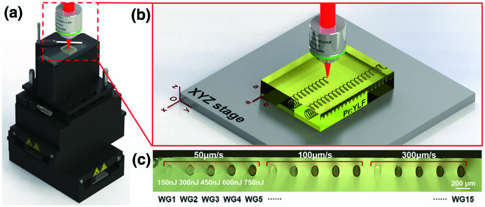
    Figure 1.(a) Schematic illustration of the XYZ translation stage for waveguide fabrication using fs-laser helical inscription. (b) Schematic of fabrication process of waveguides. (c) Microscopic photographs of waveguide cross sections. The fabrication parameters are shown in (c).

    Using a computer controlled XYZ translation stage with submicron spatial resolution, the Pr:YLF crystal is translated perpendicular to the fs-laser beam along the x axis of the stage while moving circularly in the yz plane, following the designed helical trajectory, as shown in Fig. 1(b). The fabricated structures are therefore oriented along the a axis of the crystal, which allows light propagating in the plane perpendicular to the c crystallographic direction for both σ (E//a) and π (E//c) polarizations. The average laser powers deposited on the sample change from 0.15 mW to 0.75 mW in steps of 0.15 mW, corresponding to pulse energies ranging from 150 nJ to 750 nJ with a step of 150 nJ. The velocities (in the vertical yz plane) are designed to be 50 µm/s, 100 µm/s, and 300 µm/s, corresponding to rotation velocities around 1 rad/s, 2 rad/s, and 6 rad/s, respectively. Meanwhile, a minor movement of 3 µm for each cycle in the horizontal x direction is chosen, i.e., the pitch of the helix is set to be 3 µm. Under these conditions, 15 structures are inscribed with the central depth of 200 µm under the surface [Fig. 1(c)]. The designed diameter of the structures is 100 µm (Supplementary Material). After laser inscription, the crystal is polished on the sides to 10 mm to reveal the waveguides. It should be pointed out that for waveguides with the rotation velocities of 1 rad/s, 2 rad/s, and 6 rad/s, the fabrication times are around 5.8 h, 2.9 h, and 1 h, respectively, which can be significantly reduced by increasing the pitch length while keeping the good properties of the waveguides (Fig. S1, Supplementary Material).

    The guiding behaviors of these cladding structures including supported spatial propagation modes and propagation losses together with their polarization dependence at visible wavelengths are experimentally characterized with a typical end-face coupling arrangement. For this purpose, a linearly polarized He–Ne laser is used as a laser source since its operated wavelength of 632.8 nm is approximate to the laser emission line of Pr:YLF, enabling us to know the performances of the fabricated waveguides at the lasing wavelength. The laser is focused and coupled into the waveguides with a lens (f=40mm) after passing through a half-wave plate, which is employed to investigate the wave-guiding behaviors in both σ and π polarizations. The lens gives a focal spot with a diameter of around 20 µm. The output light is directed through a 20× microscope objective and then imaged onto a CCD camera to collect the propagating modes. The propagation losses of the waveguides under 632.8 nm are investigated (Supplementary Material). Additionally, in order to further investigate the guiding ability of the fabricated structures at longer wavelength, an LD at 1064 nm is also applied as the laser source, and, likewise, the out-coupled modal profiles from the waveguides are acquired.

    Micro-structural lattice changes induced by fs laser are investigated by monitoring the confocal µ-PL spectra of the Pr3+ ions with a fiber-coupled confocal microscope (WITec alpha300 R). A 0.5 mW continuous-wave (cw) radiation from a high-performance single frequency diode pumped laser at 488 nm is focused to a diffraction-limited spot size via a 100× microscope objective lens with NA=0.9. Scattered luminescence emission is then back-collected with the same microscope objective and, after passing through a series of filters and a confocal pinhole, analyzed by a 300 mm focal length spectrometer (UHTS 300) with a 150 grooves/mm grating. The signals are eventually detected using a CCD thermoelectrically cooled to 60°C. An XYZ motorized sample stage with a spatial resolution of 300 nm is used so that the excitation spot could scan continuously to obtain 2D mappings of Pr3+ spectral properties including emitted intensity, peak position, and bandwidth.

    For waveguide laser generation, a commercially available fiber-coupled InGaN-LD operating at 444 nm is used in this work as a pump source. After being collimated, the pump beam is adjusted with a linear polarizer to pump the waveguides in the π polarization. An aspheric lens is applied to couple the pumping laser into the waveguide. Two dielectric plane mirrors are end-butted to the waveguide facets to form a typical Fabry–Perot cavity. For orange laser oscillation, the input mirror is designed to have a high transmission (>93%) at the 444 nm pump wavelength and a high reflectivity (>99%) at the orange laser wavelength. The output coupler has a transmission of about 9% at the considered orange laser wavelength and a more than 88% transmission at green and red spectral regions for suppressing these high-gain emissions. Under this configuration, the laser cavity is highly compact with a physical length of 10 mm, equal to that of the waveguides. The output signal from the waveguide, which is a mixing of residual transmitted pump light and the laser emission, is collimated with a microscope objective and then separated with a filter. Eventually, the waveguide laser emitting in the orange band is detected to evaluate the performance of such an integrated laser device. The experimental setup is schematically shown in Fig. S2 in Supplementary Material.

    Additionally, a waveguide is fabricated with classical discrete inscription, and its performances are investigated and compared with the one fabricated with the helical inscription (Fig. S3, Supplementary Material).

    3. Results and Discussion

    Figure 1(c) presents the cross-sectional images of the produced structures, which are referred to as WG1–WG15 in the following. These structures show elliptical geometries with major and minor axes of 150 µm and 100 µm, respectively. Such an extension along the vertical direction is ascribed to the refraction of the laser beam on the sample air surface. These structures are deeply embedded inside the sample without any evident damage either in the core areas or in the bulk outside the claddings, highlighting the unique capability of FLI for internal micro-fabrication. For structures fabricated with low pulse energy of 150 nJ, i.e., WG1, WG6, and WG11, weak modifications are produced on the fs-laser-induced tracks regardless of the used scanning velocity. In contrast, distinct guiding boundaries are formed regarding the structures fabricated with relatively high laser energy, and dark core regions are observed, which can be attributed to the confinement of illumination light, indicating preliminarily their capability for light field restriction.

    Polarization analyses of the waveguides are performed by measuring all-angle output power by using an end-coupling system. As pictured in Fig. 2(a), the waveguide is found with support guidance under arbitrary polarizations, and the maximum output powers are observed at 0° and 180° (corresponding to π polarization), while the minimum values are obtained at 90° and 270° (corresponding to σ polarization). Such anisotropic behaviors indicate slight polarization sensitivity of the waveguides, which is mainly due to the anisotropy of the Pr:YLF crystal along the a and c axes and also the asymmetric geometry of the structures. Results are similar for all cladding waveguides.

    (a) Polarization analysis of the transmitted power for the helically inscribed cladding waveguide WG2. (b) Measured propagation losses of the waveguides at 632.8 nm under both π and σ polarizations. The fragments of waveguide claddings from (c) WG2, (d) WG3, (e) WG4, and (f) WG5.

    Figure 2.(a) Polarization analysis of the transmitted power for the helically inscribed cladding waveguide WG2. (b) Measured propagation losses of the waveguides at 632.8 nm under both π and σ polarizations. The fragments of waveguide claddings from (c) WG2, (d) WG3, (e) WG4, and (f) WG5.

    The loss dependence of the waveguides on the fabrication parameters and polarizations is further determined by assuming a coupling efficiency of 100% between the injected light and the waveguide. The results, as shown in Fig. 2(b), reveal that in general reduced propagation losses are obtained under π polarization. Meanwhile, one can also note that the waveguides fabricated with 150 nJ pulse energy exhibit relatively high propagation losses, >0.5dB/cm, due to the aforementioned weak RI modifications in the fs-laser-irradiated claddings. The propagation losses decrease dramatically with the irradiated pulse energy increase to 300 nJ, and the structures produced with 50 µm/s scan speed have the lowest loss compared with the others since decreased scan speed is frequently beneficial to increasing the micro-modifications in the laser-induced cladding regions, leading to high index contrast between the guiding core and its boundary and further enhancing light confinement of the waveguides. Under fixed scan speed of 50 µm/s, further increment of pulse energy results in slight rising of waveguide losses. The fundaments responsible for such a phenomenon can be obtained with detailed investigation of the fs-laser modification behaviors under diverse irradiated pulse energies. Figures 2(c)2(f) show the fragments of waveguide claddings inscribed with pulse energy increasing from 300 nJ to 750 nJ at a scan speed of 50 µm/s (i.e., WG2–WG5). In contrast to the smooth modification of WG2, higher pulse energies used for WG3–WG5 induce more severe damages and even cracks within their claddings, which are prone to introduce additional scattering of the light field within the waveguides, leading to larger propagation losses. Therefore, the optimal parameters for the damage-free waveguide fabrication by fs-laser helical inscription are obtained with pulse energy of 300 nJ and a scan speed of 50 µm/s. From this waveguide, the lowest propagation loss is realized with a value of 0.12 dB/cm for multimode guiding. This makes the structures produced in our work outstanding platforms for passive wave guiding and active waveguide laser generation.

    Regarding investigations on the guided propagating modes, all 15 waveguides show strong optical confinement under both 633 nm and 1064 nm. As representatives, Figs. 3(a) and 3(b) display the normalized intensity distributions of propagating modes obtained from WG2 under π-polarized 633 nm and 1064 nm pumping. As it can be seen, the mode boundaries are very clear, and no light leakage occurred, revealing the ability of the fabricated waveguides for strong light confinement. Moreover, the waveguide has multimode at the near-infrared wavelength of 1.06 µm, which demonstrates their potential for wave guiding at longer wavelength, even under mid-infrared wavelengths, making the fabricated waveguides promising for guiding in the whole mid-infrared transmission range of YLF. Identical results can be obtained under the excitation of a σ-polarized pump beam, and the mode distributions do not exhibit significant polarization dependence.

    Spatial propagating modes from WG2 under π-polarized 633 nm and 1064 nm pumping.

    Figure 3.Spatial propagating modes from WG2 under π-polarized 633 nm and 1064 nm pumping.

    The µ-PL spectrum, as shown in Fig. 4(a), exhibits various emission lines throughout the visible spectral range from cyan to deep red. The emission is dominated by the transitions starting from the P3j level to the final state of H34, H35, H36, F32, F33, and F34, as labeled in Fig. 4(a). A dominant emission of Pr3+ is found in the red at 640.9 nm in σ polarization, corresponding to the P30F32 transition. Concerning emissions in the orange, two intense lines with P30H36 energy transfer are noted, which are related to the wavelengths of 605.8 nm and 608.5 nm in π and σ polarization, respectively. Micro-structural lattice changes induced during FLI are investigated by monitoring the luminescence properties of the emission line at 641nm. Here, the 641 nm emission line is used since it is sharp and spatially isolated from other transitions, which could provide noticeable variation of µ-PL properties. Figure 4(b) shows the µ-PL spectra obtained from three typical zones which are Pr:YLF bulk, the helical track constituting the cladding, and the guiding core far from the cladding area. The µ-PL spectrum generated from the track is most noticeable for its drastic quenching in the luminescence intensity, with a great reduction of 74% when compared to that obtained from the unmodified bulk. This is a clear indication that strong optical-breakdown damage is caused by FLI in these areas. In contrast, the µ-PL spectrum obtained inside the waveguide region is nearly identical to that of the bulk.

    (a) Confocal µ-PL spectrum of the Pr3+ ions obtained under 488 nm excitation at the waveguide cross section. (b) Comparison of the µ-PL spectra around 641 nm obtained from the bulk (red line), the guiding core (blue line), and the helical track (black line).

    Figure 4.(a) Confocal µ-PL spectrum of the Pr3+ ions obtained under 488 nm excitation at the waveguide cross section. (b) Comparison of the µ-PL spectra around 641 nm obtained from the bulk (red line), the guiding core (blue line), and the helical track (black line).

    Further investigations on the confocal mappings of Pr3+ luminescence are performed to get complete knowledge on the spatial variation of the peak intensity, frequency, and bandwidth of the emission line at 641 nm and further on the spatial distribution of micro-structural changes. The corresponding integration region is marked in Fig. 4(a). Firstly, 2D mappings of the µ-PL are measured from large areas covering the waveguide cross section and its surroundings, as schematized with the red surface in Fig. 5(a). The results are displayed in Figs. 5(b)5(d). It is evidenced that, in the waveguide cross section, remarkable decrease of the peak intensity appears continuously along the laser modified cladding and expands slightly to its vicinity [as shown in Fig. 5(b)], supporting the presence of a high density of lattice defects and imperfections in these regions. Meanwhile, in the cladding area, a very localized blue-shift of the emission line can be observed with a maximum value of around 0.17nm [see Fig. 5(c)]. This blue-shift is associated with expansive stress induced by FLI and further indicates the presence of a local lattice distortion. Simultaneously, as shown in Fig. 5(d), the emission peak broadens at the laser modified cladding area, with an increase of around 0.14 nm in the FWHM, further suggesting the partial lattice disorder at the cladding location. Furthermore, as can be observed, the µ-PL spectral properties are almost unchanged inside the guiding core, not only in terms of peak intensity but also in energy shift and bandwidth, as previously demonstrated by Fig. 4(b). Additionally, Figs. 5(e)5(g) show the µ-PL mapping images obtained along the surface indicated in blue in Fig. 5(a). As shown in the insets of Fig. 5(a), the blue surface is parallel to the xy plane on one side and in the center of the structure. It can be seen that the blue surface covers a part of the waveguide area, several sections of the fabricated loops, and a part of unmodified bulk. Again, the results confirm the spatially localized lattice modifications induced by FLI. More importantly, it should be noted that the loops are closely arranged with negligible gaps in between tracks, forming a continuous boundary of the waveguide.

    (a) Schematic showing of a waveguide structure and the areas for 2D µ-PL mappings, insets in (a) are the top and front views of the waveguide structure, indicating clearly the position of red and blue surfaces. (b), (e) Spatial dependence of the intensity, (c), (f) energy shift, and (d), (g) the change in FWHM of the 641 nm emission line obtained from a wide area covering the waveguide cross section and several sections of the loops, as indicated with the planes in red and blue in (a), respectively.

    Figure 5.(a) Schematic showing of a waveguide structure and the areas for 2D µ-PL mappings, insets in (a) are the top and front views of the waveguide structure, indicating clearly the position of red and blue surfaces. (b), (e) Spatial dependence of the intensity, (c), (f) energy shift, and (d), (g) the change in FWHM of the 641 nm emission line obtained from a wide area covering the waveguide cross section and several sections of the loops, as indicated with the planes in red and blue in (a), respectively.

    Therefore, from the comprehensive study of 2D µ-PL measurements, one can safely conclude that (i) the low-index waveguide boundary is caused by highly localized structural modifications including defects, distortion, disorder, and expansive stress in the fs-laser-induced tracks; (ii) in the guiding zone, negligible lattice damage is produced, and hence the optical properties of Pr:YLF crystal are expected to be well preserved, making the waveguide even promising for laser generation; (iii) the waveguide wall of WG2 is continuous, not only in the plane perpendicular to the propagation direction but also in the parallel direction of propagation. These features combined together are believed to be responsible for low propagation loss of the waveguide.

    Laser emissions in orange are obtained from the fabricated waveguides in the cw regime at room temperature. The inset of Fig. 6(a) shows the normalized spatial intensity distribution of the output laser mode obtained from WG2, which, as expected, is highly multimode. The laser emission spectrum centered at 604 nm is shown in Fig. 6(a), corresponding to the emission line correlated to the P30H36 transition of Pr3+ ions in π polarization. The 604 nm lasers have been demonstrated previously in the Pr:YLF waveguides fabricated by using the classical discrete inscription approach and liquid phase epitaxy[11,24,25]. Waveguide laser emission at 607 nm has not been obtained. It has been found that the actual emission cross section (after excluding the influence of reabsorption) at 604 nm (19.6×1020cm2) is slightly higher than that at 607 nm (15.7×1020cm2) at room temperature[23]. This, in company with the relatively low pumping laser powers used for waveguide laser generation, might be possible reasons responsible for the prior laser operation at 604 nm in the waveguide structures. The obtained waveguide laser power as a function of incident pumping power is shown in Fig. 6(b). Optimization of the waveguide laser system operating at 604 nm is obtained from WG2, which gives a maximum output power of 120.6 mW with an incident pump light threshold of 119.8 mW and a slope efficiency of 16.6%. For WG3 and WG4, comparable laser performances are obtained with a maximum output power of around 104 mW and pumping thresholds of 125.6 mW and 129.9 mW, respectively, corresponding to slope efficiencies of 14.5% and 14.1%. Due to the relatively high propagation loss, a higher laser threshold of 161.6 mW is observed from WG5, and the maximum output power (81 mW) and the slope efficiency (11.8%) are lower. Compared with the previous work on Pr:YLF bulky lasers, our waveguide laser systems, although they do not have as high of a performance, show prominent merits in terms of highly compact lasing oscillation cavity and low threshold pump power of 604 nm radiation[20,21,23]. Further comparison with the previously demonstrated Pr:YLF cladding waveguide lasers shows that the ones produced here are more advantageous as integrated laser devices for reduced pumping thresholds and enhanced efficiencies[11,25].

    (a) Optical spectrum of waveguide laser centered at 604 nm. (b) Output laser power of the waveguides as a function of incident pump power. The inset of (a) shows the normalized spatial intensity distribution of the output laser mode.

    Figure 6.(a) Optical spectrum of waveguide laser centered at 604 nm. (b) Output laser power of the waveguides as a function of incident pump power. The inset of (a) shows the normalized spatial intensity distribution of the output laser mode.

    4. Conclusion

    In summary, we report on the first realization, to the best of our knowledge, of cladding waveguides in Pr:YLF crystal by FLI using a scheme in which the substrate is moved along a helical trajectory. Such a helical inscription scheme, in company with the optimized parameters (300 nJ pulse energy and 50 µm/s scan speed), is proved to provide waveguides with superior properties in terms of smooth and continuous cladding contour, intact guiding core, strong mode confinement under orthogonal polarizations in a wide spectral range, and, most importantly, low propagation losses (0.12 dB/cm for multimode guiding). π-polarized 604 nm waveguide lasers are realized under InGaN-LD excitation at 444 nm. Based on the most optimized waveguide structure, a highest output power of 120.6 mW is achieved with pumping threshold of 119.8 mW and slope efficiency of 16.6%. Further optimization of the new inscribing procedure is still necessary in aspects of waveguide geometry to obtain a symmetric mode profile and enable a higher coupling efficiency to the waveguide. Nevertheless, the results of this work show that the waveguides in Pr:YLF produced with fs-laser helical inscription enable compact and robust orange laser sources with good performance. Furthermore, concerning the flexibility and applicability of the helical inscription in the structural view, it is believed that more complex structures such as waveguide splitters and near-surface waveguides (Fig. S4, Supplementary Material) can be fabricated by specially designing the processing trajectories.

    References

    [1] D. Choudhury, J. R. Macdonald, A. K. Kar. Ultrafast laser inscription: perspectives on future integrated applications. Laser Photon. Rev., 8, 827(2014).

    [2] K. Sugioka, J. Xu, D. Wu, Y. Hanada, Z. K. Wang, Y. Cheng, K. Midorikawa. Femtosecond laser 3D micromachining: a powerful tool for the fabrication of microfluidic, optofluidic, and electrofluidic devices based on glass. Lab Chip, 14, 3447(2014).

    [3] Y. C. Jia, S. X. Wang, F. Chen. Femtosecond laser direct writing of flexibly configured waveguide geometries in optical crystals: fabrication and application. Opto-Electron. Adv., 3, 190042(2020).

    [4] K. Sun, D. Z. Tan, X. Y. Fang, X. T. Xia, D. J. Lin, J. Song, Y. H. Lin, Z. J. Liu, M. Gu, Y. Z. Yue, J. R. Qiu. Three-dimensional direct lithography of stable perovskite nanocrystals in glass. Science, 375, 307(2022).

    [5] A. Rodenas, G. A. Torchia, G. Lifante, E. Cantelar, J. Lamela, F. Jaque, L. Roso, D. Jaque. Refractive index change mechanisms in femtosecond laser written ceramic Nd:YAG waveguides: micro-spectroscopy experiments and beam propagation calculations. Appl. Phys. B, 95, 85(2009).

    [6] F. Chen, J. R. V. de Aldana. Optical waveguides in crystalline dielectric materials produced by femtosecond-laser micromachining. Laser Photon. Rev., 8, 251(2014).

    [7] A. G. Okhrimchuk, A. V. Shestakov, I. Khrushchev, J. Mitchell. Depressed cladding, buried waveguide laser formed in a YAG : Nd3+ crystal by femtosecond laser writing. Opt. Lett., 30, 2248(2005).

    [8] R. N. Li, L. F. Sun, Y. J. Cai, Y. Y. Ren, H. L. Liu, M. D. Mackenzie, A. K. Kar. Near-infrared lasing and tunable upconversion from femtosecond laser inscribed Nd,Gd:CaF2 waveguides. Chin. Opt. Lett., 19, 081301(2021).

    [9] Y. Y. Ren, L. M. Zhang, H. G. Xing, C. Romero, J. R. V. de Aldana, F. Chen. Cladding waveguide splitters fabricated by femtosecond laser inscription in Ti:sapphire crystal. Opt. Laser Technol., 103, 82(2018).

    [10] H. L. Liu, Y. C. Jia, J. R. V. de Aldana, D. Jaque, F. Chen. Femtosecond laser inscribed cladding waveguides in Nd:YAG ceramics: fabrication, fluorescence imaging and laser performance. Opt. Express, 20, 18620(2012).

    [11] S. Muller, T. Calmano, P. Metz, N. O. Hansen, C. Krankel, G. Huber. Femtosecond-laser-written diode-pumped Pr:LiYF4 waveguide laser. Opt. Lett., 37, 5223(2012).

    [12] Y. P. Peng, X. Zou, Z. Y. Bai, Y. X. Leng, B. X. Jiang, X. W. Jiang, L. Zhang. Mid-infrared laser emission from Cr:ZnS channel waveguide fabricated by femtosecond laser helical writing. Sci. Rep., 5, 18365(2015).

    [13] G. Salamu, F. Jipa, M. Zamfirescu, N. Pavel. Cladding waveguides realized in Nd:YAG ceramic by direct femtosecond-laser writing with a helical movement technique. Opt. Mater. Express, 4, 790(2014).

    [14] B. Fang, S. Gao, Z. Wang, S. Zhu, T. Li. Efficient second harmonic generation in silicon covered lithium niobate waveguides. Chin. Opt. Lett., 19, 060004(2021).

    [15] Y. Niu, L. Yang, D. Guo, Y. Chen, X. Li, G. Zhao, X. Hu. Efficient 671 nm red light generation in annealed proton-exchanged periodically poled LiNbO3 waveguides. Chin. Opt. Lett., 18, 111902(2020).

    [16] C. Pang, R. Li, Z. Li, N. Dong, J. Wang, F. Ren, F. Chen. Multi-gigahertz laser generation based on monolithic ridge waveguide and embedded copper nanoparticles. Chin. Opt. Lett., 19, 021301(2021).

    [17] T. Calmano, S. Muller. Crystalline waveguide lasers in the visible and near-infrared spectral range. IEEE J. Sel. Top. Quantum Electron., 21, 401(2015).

    [18] C. Grivas. Optically pumped planar waveguide lasers: part II: gain media, laser systems, and applications. Prog. Quantum Electron., 45–46, 3(2016).

    [19] C. Krankel, D. T. Marzahl, F. Moglia, G. Huber, P. W. Metz. Out of the blue: semiconductor laser pumped visible rare-earth doped lasers. Laser Photon. Rev., 10, 548(2016).

    [20] Y. J. Cheng, B. Xu, B. Qu, S. Y. Luo, H. Yang, H. Y. Xu, Z. P. Cai. Comparative study on diode-pumped continuous wave laser at 607 nm using differently doped Pr3+:LiYF4 crystals and wavelength tuning to 604 nm. Appl. Opt., 53, 7898(2014).

    [21] Y. S. Zhang, L. B. Zhou, T. Zhang, Y. Q. Cai, B. Xu, X. D. Xu, J. Xu. Blue diode-pumped single-longitudinal-mode Pr:YLF lasers in orange spectral region. Opt. Laser Technol., 130, 106373(2020).

    [22] S. Y. Luo, X. G. Yan, Q. Cui, B. Xu, H. Y. Xu, Z. P. Cai. Power scaling of blue-diode-pumped Pr:YLF lasers at 523.0, 604.1, 606.9, 639.4, 697.8 and 720.9 nm. Opt. Commun., 380, 357(2016).

    [23] X. Lin, Y. Zhu, S. Ji, W. Li, H. Xu, Z. Cai. Highly efficient LD-pumped 607 nm high-power CW Pr3+: YLF lasers. Opt. Laser Technol., 129, 106281(2020).

    [24] W. Bolanos, G. Brasse, F. Starecki, A. Braud, J. L. Doualan, R. Moncorge, P. Camy. Green, orange, and red Pr3+:YLiF4 epitaxial waveguide lasers. Opt. Lett., 39, 4450(2014).

    [25] H. L. Liu, S. Y. Luo, B. Xu, H. Y. Xu, Z. P. Cai, M. H. Hong, P. F. Wu. Femtosecond-laser micromachined Pr:YLF depressed cladding waveguide: Raman, fluorescence, and laser performance. Opt. Mater. Express, 7, 3990(2017).

    [26] C. Grivas. Optically pumped planar waveguide lasers, part I: fundamentals and fabrication techniques. Prog. Quantum Electron., 35, 159(2011).

    [27] V. A. Amorim, J. M. Maia, D. Viveiros, P. V. S. Marques. Loss mechanisms of optical waveguides inscribed in fused silica by femtosecond laser direct writing. J. Lightwave Technol., 37, 2240(2019).

    Yingying Ren, Zemeng Cui, Lifei Sun, Chao Wang, Hongliang Liu, Yangjian Cai. Laser emission from low-loss cladding waveguides in Pr:YLF by femtosecond laser helical inscription[J]. Chinese Optics Letters, 2022, 20(12): 122201
    Download Citation