Abstract
A monolithic lens-window-prism (LWP) device, made of lithium fluoride (LiF) or magnesium fluoride (MgF2), was proposed. When either of the devices was fixed onto one end of a gas cell filled with Xe, it becomes a “wedge-crystal”-like device and was used to convert a 1 MHz femtosecond 347 nm laser to its third harmonic radiation at 10.7 eV. This led to an improved beam profile and a more compact and less lossy configuration. A stable output power of ~11 μW was demonstrated for 2 h using LiF-LWP. In addition, MgF2-LWP was also verified for its practicability at 10.7 eV.Vacuum ultraviolet (VUV) beam sources (, i.e., ) are indispensable for laser-based angle-resolved photo-emission spectroscopy (ARPES). These high photon energies can overcome the typical work functions ranging from 4.5 to 4.8 eV[1] and allow larger inelastic mean-free electron paths compared with those enabled by radiation sources (typically, 20–100 eV) based on high-harmonics generation (HHG), which thus can improve the bulk sensitivity of ARPES[2]. However, due to the lack of suitable gain media, they usually cannot be generated directly. Accordingly, nonlinear frequency conversion technologies have to be resorted to, where extracting the generated VUV beam from the fundamental laser driver is quite challenging.
In terms of solid-state nonlinear media, potassium fluoro-beryllo-borate (KBBF) crystals are the exclusive ones that can provide the required phase matching conditions in the VUV region and have enabled the generation of beams at 177.3 nm (6.99 eV)[3], 165 nm (7.51 eV)[4], and 149.8 nm (8.28 eV)[5]. Because KBBF is usually used as a prism-coupled device (PCD), the generated VUV beam propagates in a different direction relative to that of the fundamental laser driver, and no additional extraction is needed[3–5]. For the generation of still shorter wavelengths, noble gases have to be adopted as the nonlinear media. In this case, window-free configurations or gas nozzles are usually used because of the lack of suitable materials that can effectively transmit the wavelength below 105 nm (11.8 eV). Some reflective optics with limited reflectivity are used to extract the generated harmonic radiations, such as fused silica plates[6], silicon carbide[7], and Mo/Si mirrors[8]. Subsequently, with the help of a monochromator and thin metal filters, one can select the desired harmonic. Inevitably, this kind of window-free configuration leads to significant noble gases consumption, and redundant optics introduce losses for the beam line. Fortunately, for wavelengths longer than (11.8 eV) and (10.8 eV), which are cutoff wavelengths of lithium fluoride (LiF) and magnesium fluoride (), respectively[9], transmission optics (such as windows, lenses, and prisms) made of LiF and can be considered. Currently, there have been some reports about this, but exclusively using LiF[10–12], and no employment of around 10.7 eV has been reported to the best of our knowledge. Compared to LiF, is interesting for its high hardness and high birefringence. Furthermore, is much easier to fabricate than LiF is. Usually, windows are used for isolation between noble gases and the vacuum chamber, lenses for collimation, and prisms for separating the generated VUV beam from the fundamental driver radiation, which means that the generated VUV beam will encounter 4–6 LiF or surfaces along its path, depending on the number of LiF or optics used. However, the transmission of LiF is susceptible to the surface flatness (i.e. the quality of the polishing), storage conditions, and temperatures[13–15]. Especially, it is worth paying more attention to the losses from the surface itself, which actually come from not only the Fresnel losses but also from the irregular tiny surface waviness, polishing materials, polishing methods, cleaning materials, and thin layers left behind on the surface[13,14]. The divergence between theoretical Fresnel losses and the actual ones is much more significant at shorter wavelengths than at longer ones[14]. Therefore, there is an incentive to decrease the number of LiF optics used, accordingly, the number of LiF surfaces that are on the VUV beam path in order to avoid multiple uncertainties on the transmission and increase the total transmission, which in turn can make the overall system more compact, stable, and cost effective. One more concern lies in the beam profile of the generated VUV beam. For the intended purposes of ARPES applications, ideally, the generated beam has a circular shape. In our previous work[12], due to the large apex angle () of the used prism, the relative broadband width of the input fundamental laser driver, and the large dispersion of LiF around 115.6 nm, the generated 10.7 eV beam was elliptical. This issue could have been avoided had a fundamental laser driver with a narrow bandwidth picosecond output been used[11].
In this manuscript, we report on a monolithic lens-window-prism (LWP) device made of either LiF or , the use of which improved performances, such as the beam profile and losses, as well as allowed for a more compact setup. Fixing the LWP onto one end of a gas cell filled with Xe turned the device into being “wedge-crystal” like. Functionally, it works like the frequently used crystals that convert the input frequency into harmonics. Specifically, by making the apex angle much smaller, we successfully obtained a nearly circular beam shape instead of the previously reported elliptical one[12]. The LiF and LPW devices yielded similar results at 10.7 eV. To the best of our knowledge, this is the first report on the use of optics around their cutoff wavelength region. Experimentally, a homemade femtosecond laser at 347 nm with a repetition rate of 1 MHz was used as a fundamental laser driver, and an average power of at 10.7 eV was achieved, corresponding to a conversion efficiency of . Additionally, VUV power decay was observed for both LiF-LWP and -LWP devices when placed in a chamber under vacuum conditions. However, by filling this chamber with nitrogen, the power stability was significantly improved, and no indication of decay was observed. As an example, a stable output power of with LiF-LWP was demonstrated for 2 h.
Sign up for Chinese Optics Letters TOC. Get the latest issue of Chinese Optics Letters delivered right to you!Sign up now
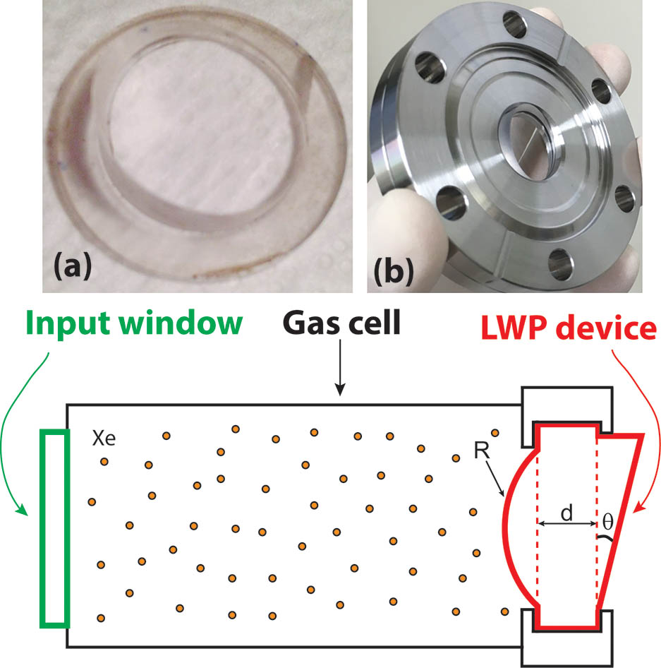
Firstly, we would like to give a brief introduction on the developed monolithic LWP device made of LiF and , as shown in Fig. 1. For a better understanding, one can imagine that it consists of three parts: a plano-convex lens on one side with a radius of curvature R to re-collimate the beam, a plano-plano window with a thickness to isolate the gas cell from the chamber onto which it would be attached, and a right angle prism with apex angle to separate the generated VUV beam from the fundamental laser driver one. In our case, the three parameters were (134.82 mm), (2 mm), and (20°) for LiF-LWP (-LWP), respectively. Although the two radii of curvatures were different for LiF-LWP and -LWP, they yielded a same focal length of at a wavelength of 115.6 nm, given their different refractive indices. The reason why we prepared an -LWP, in addition to the LiF-LWP one, was to test whether or not optics can be used so close to their cutoff wavelength. The optical axis of is parallel to the laser propagation direction inside the gas cell shown in Fig. 1, so there is no birefringence expected. The inset (a) in Fig. 1 shows the photograph of the custom made LiF-LWP, and the inset (b) in Fig. 1 shows the integrated flange that can be fixed onto the other end of the gas cell. The lower part of Fig. 1 shows the schematic diagram of the wedge-crystal-like gas cell, where the noble gas inside was static as the experiments were carried out. The input end is a commercially available antireflective (AR) coated ultraviolet fused silica (UVFS) window (4 mm in thickness).

Figure 1.Schematic diagram of the “wedge-crystal”-like gas cell (lower part), integrated with the monolithic lens-window-prism (LPW) device. (a) A photograph of the custom-made LiF-LPW device. (b) The integrated flange that can be fixed onto the other end of the gas cell.
Figure 2 shows the schematic diagram of the experimental setup for the generation of the 10.7 eV beam source. The quasi-monolithic gas cell ( in length) was attached to a chamber. The fundamental laser driver was a homemade femtosecond 347 nm ultraviolet (UV) laser with a repetition rate of 1 MHz[12], which could deliver an average power of up to 10 W and was focused into the gas cell using a lens with a focal length of 150 mm. The gas cell was filled with Xe. After passing through the LiF-LWP, the generated VUV beam was collimated and separated from the fundamental driver thanks to the geometry of the LWP, and the unconverted fundamental UV laser was directed to a beam dump or reflected by a mirror onto a power meter for measurements. The generated VUV beam was firstly incident onto a movable fluorescence plate to verify its generation. After ascertaining that the desired harmonic was generated, the fluorescence plate was removed from the beam path, and the average power could be measured with a phototube (Hamamatsu Photonics: R1187), which has a spectral response from 115 to 200 nm with a peak response at 130 nm.
Figure 2.Schematic diagram of the experimental setup for the generation of a 10.7 eV beam source. The input laser is from a homemade 347 nm femtosecond laser with a repetition rate of 1 MHz. (a) The previously obtained beam profile. (b) The beam profile obtained with the LWP device. Phototube: Hamamatsu Photonics R1187.
For experiments, we firstly tested the beam profile obtained with the LWP. The results are shown in Fig. 3. With the help of a fluorescence plate and a CCD camera, the beam profiles were acquired for different UV input powers ranging from 0.5 to 2.5 W (pulse energy 0.5 to 2.5 μJ), with an exposure time of 10 ms. Figure 3 visibly shows almost circular beam profiles and the brightness increasing with increasing input powers. The exact power was not characterized, as the phototube was not available at the time this test was carried out. What is noteworthy is that a VUV beam can be generated with pulse energy as low as 0.5 μJ, which means a laser driver with a higher repetition rate of or more could be used. The beam profile was also compared to the one obtained in our previous work, as shown in Fig. 2(a)[12]. Since the fundamental laser driver was a relatively broadband femtosecond laser, the generated VUV source was expected to inherit this same characteristic. Therefore, spatial dispersion would be introduced as the beam passes through the prism. The smaller the apex angle of the prism is, the more circular the beam profile is. In this proof-of-principle experiment, we considered the size of our chamber (40 cm in length) and the necessary angle of separation between the fundamental driver and the VUV beam to be directed towards the beam dump and the phototube correspondingly, and so the angle of the prism used was 20°. If the distance between the gas cell and the real sample under test was much longer, one could consider using an LWP device with a smaller apex angle (for example, 10° or 5°), which could lead to a further improved circular beam profile. In experiments, although higher powers of up to 10 W were available, they were not used here in order to preserve the lifetime of the LWPs. Based on our previous experience and the trend shown in Fig. 3, we believe that much higher VUV power could be expected if a high-power UV laser was used.
Figure 3.Beam profiles on the fluorescence plate taken with a CCD camera when different UV powers were used.
Next, we tested the long-term stability of the generated VUV beam, which would be critical for the intended applications. Different from our previous experiments, we used a phototube instead of a photodiode. Phototubes have the advantage of suppressing the spectral response at the UV band, which, hence, can get rid of the influence of background signals. A picoammeter was used to read out the signal intensity, and the real power could be calculated with a spectral response of 4 nA/μW (provided by the manufacturer). We confirmed at least more than 3 orders of magnitude suppression of the UV and visible light background. So, the subtraction of the background from the main signal is no longer necessary. Experimentally, both LiF-LWP and -LWP were tested. Figure 4 shows the results for an input UV power of , where the VUV output decayed rapidly. For LiF-LWP and -LWP, the decay times are found to be 62 and 59 min using exponential fitting, respectively. The transmitted 347 nm laser power was simultaneously monitored by inserting a movable mirror and guiding the beam to a power meter, as shown in the Fig. 2, and no obvious decay was observed. This data was not acquired continuously, only every 30 min, so it is not shown here.
Figure 4.Experimentally measured decay of the average powers using LiF-LWP and -LWP in vacuum conditions. The black lines are fitted results using exponential decay. For both cases, the normalized intensity 1.0 corresponds to a real power of 8 μW.
Although we do not know the exact origin of the rapid VUV power decay, there are a few suggested reasons for this. One is the absorption of moisture from the environment[16,17]. Another is the generation of ozone around the surface of LiF and via photochemical reaction processes when the VUV beam encounters oxygen[18,19]. Also, if the laser system is operated under vacuum conditions, organic molecules, like outgassing from components and materials, can accumulate and be deposited onto the irradiated optical surfaces by interaction with the high-energy photons. This is the so-called laser-induced contamination (LIC)[20,21]. To thoroughly investigate the definitive reason is difficult and out of the scope of this work. Indeed, similar issues occur with nonlinear crystals, like beta barium borate (BBO) and KBBF, when they are used to generate UV or VUV beams. To resolve this problem, oxygen and inert gases are usually used in the beam path[19,22].
To improve the stability of the generated VUV source, we used nitrogen (approximatively 150 Pa) to fill the chamber after vacuum evacuation. The result is shown in Fig. 5, where LiF-LWP was used. The stability was visibly improved compared with that shown in Fig. 4. Within 2 h, there was no indication of the VUV power decreasing. The average power was around . With an input power of considered, the corresponding conversion efficiency was on target. This efficiency was somewhat lower than that reported in Ref. [12], which was on target (). We believe two factors were responsible for this: one was the much lower input powers used, 1.3 versus 5 W, and the other one was that only Xe was used in the present work instead of the hybrid Xe/Ar gas mixture in Ref. [12], which allowed a four times higher yield. Considering these factors, we believe that the demonstrated LWP device gives much better results. Here, for rough estimations, we integrated the intensities in Fig. 3 and estimated the powers for each case. It is for Fig. 3(e). By fitting all five cases in Fig. 3, we found a proportional relationship of (both the CCD camera and fluorescence plate are assumed to linearly respond to the VUV beam source), which is much weaker than expected, . Even with this relationship, if a 10 W UV laser was used, more than 300 μW could be expected on the target.
Figure 5.Average power of the 10.7 eV beam with the chamber filled with nitrogen. LiF-LWP was used here.
In conclusion, we have conceived and demonstrated a monolithic LWP device made of either LiF or , which allowed a quasi-monolithic integrated wedge-crystal-like gas cell. With this device, we have achieved an improved beam profile at a 10.7 eV beam and decreased the total losses of the overall system. Pulse energy of 0.5 μJ was sufficient to enable VUV generation at 10.7 eV. We also demonstrated that is usable in practice for a wavelength of 115.6 nm (10.7 eV) and gives a similar transmission to LiF. Although the decay in average power was observed, this issue was overcome by using nitrogen gas. As a demonstration, 2 h of stable operation was shown with an average power of , corresponding to a conversion efficiency of . Additionally, due to the required low pulse energy, we believe that repetition rates could be extended to 10 MHz or higher.
References
[1] S. Hufner. Photoelectron Spectroscopy: Principles and Applications(2003).
[2] M. P. Seah, W. A. Dench. Surf. Interface Anal., 1, 2(1979).
[3] B. Xu, L. Liu, X. Wang, C. Chen, X. Zhang, S. Lin. Appl. Phys. B, 121, 489(2015).
[4] S. Dai, M. Chen, S. Zhang, Z. Wang, F. Zhang, F. Yang, Z. Wang, N. Zong, L. Liu, X. Wang, J. Zhang, Y. Bo, D. Cui, Q. Peng, R. Li, C. Chen, Z. Xu. Laser Phys. Lett., 13, 035401(2016).
[5] T. Nakazato, I. Ito, Y. Kobayashi, X. Wang, C. Chen, S. Watanabe. Opt. Express, 24, 17149(2016).
[6] R. Klas, S. Demmler, M. Tschernajew, S. Hädrich, Y. Shamir, A. Tünnermann, J. Rothhardt, J. Limpert. Optica, 3, 1167(2016).
[7] S. Adachi, T. Horio, T. Suzuki. Opt. Lett., 37, 2118(2012).
[8] K. Ishizaka, T. Kiss, T. Yamamoto, Y. Ishida, T. Saitoh, M. Matsunami, R. Eguchi, T. Ohtsuki, A. Kosuge, T. Kanai, M. Nohara, H. Takagi, S. Watanabe, S. Shin. Phys. Rev. B, 83, 081104(2011).
[9] P. Laporte, J. L. Subtil, M. Courbon, M. Bon, L. Vincent. J. Opt. Soc. Am., 73, 1062(1983).
[10] F. Cilento, A. Crepaldi, G. Manzoni, A. Sterzi, M. Zacchigna, P. Bugnon, H. Berger, F. Parmigiani. J. Electron Spectrosc. Relat. Phenom., 207, 7(2016).
[11] Y. He, I. M. Vishik, M. Yi, S. Yang, Z. Liu, J. J. Lee, S. Chen, S. N. Rebec, D. Leuenberger, A. Zong, C. M. Jefferson, R. G. Moore, P. S. Kirchmann, A. J. Merriam, Z. Shen. Rev. Sci. Instrum., 87, 011301(2016).
[12] Z. Zhao, Y. Kobayashi. Opt. Express, 25, 13517(2017).
[13] G. W. Fynn, W. J. A. Powell. J. Phys. E: Sci. Instrum., 4, 248(1971).
[14] E. G. Schneider. Phys. Rev., 49, 341(1936).
[15] R. J. Davis. J. Opt. Soc. Am., 56, 837(1966).
[16] D. A. Patterson, W. H. Vaughan. J. Opt. Soc. Am., 53, 851(1963).
[17] H. Wada, M. Oka, K. Tatsuki, M. Saito, S. Kubota. Jpn. J. Appl. Phys., 43, L393(2004).
[18] T. Kanai, T. Kanda, T. Sekikawa, S. Watanabe, T. Togashi, C. Chen, C. Zhang, Z. Xu, J. Wang. J. Opt. Soc. Am. B, 21, 370(2004).
[19] F. Trager. Handbook of Lasers and Optics(2012).
[20] M. Hippler, P. Wagner, H. Schroeder, W. Riede. Proc. SPIE, 9952, 99520N(2016).
[21] D. Kokkinos, H. Schroeder, K. Fleury–Frenette, M. P. Georges, W. Riede, G. Tzeremes, P. Rochus. CEAS Space J., 9, 153(2017).
[22] R. Zhao, X. Fu, L. Zhang, S. Fang, J. Sun, Y. Feng, Z. Xu, Y. Wang. Appl. Opt., 56, 8973(2017).