1Center for Terahertz Waves and College of Precision Instrument and Optoelectronics Engineering, Key Laboratory of Opto-electronics Information and Technical Science, Ministry of Education, Tianjin University, Tianjin 300072, China
2School of Electrical and Computer Engineering, Oklahoma State University, Stillwater, Oklahoma 74078, USA
Surface waves (SWs) are a special form of electromagnetic waves that travel along the boundary between a metal and a dielectric. The special optical properties of SWs render them very attractive in applications, such as subdiffractional lithography, novel biochemical sensors, and ultrafast integrated circuitries. Herein, we present a review of our recent progress in excitation and manipulation of terahertz SWs due to interference or coupling between a pair of slit resonators in metasurfaces, showing the ability to devise ultrathin and compact plasmonic components.
Plasmonics and metamaterials are two emerging branches of modern optics and photonics[1,2] initiated by the inter-related discoveries of extraordinary optical transmission and perfect imaging properties of structured metal films by Ebbesen[3] and Pendry[4], respectively. In the last few decades, two-dimensional metamaterials composed of a planar and ultrathin array of optical components that possess specific electromagnetic responses, i.e., the metasurfaces, have shown unprecedented capabilities of manipulating electromagnetic waves in either the far-field or near-field[5–7]. In the far-field, practical devices of general interest, such as metalenses[8,9], perfect absorbers[10,11], polarization rotators[12], and holograms[13,14], have been successfully demonstrated[15].
In the near-field, electromagnetic energy can be guided and confined to propagate as surface waves (SWs) along the interface between a metal and a dielectric[1]. Manipulation of SWs, although challenging, is very attractive in developing next-generation ultra-compact integrated optoelectronic circuitries[16]. SWs in the optical regime, mostly known as surface plasmon polaritons (SPPs), could be tailored to form focusing spots[17], special beams[1819], or complex patterns[20,21] by metasurfaces. In the microwave range, inspired by the idea of mimicking surface plasmons (SPs) with structured surfaces[22], the so-called spoof SPPs or designer SPPs have been theoretically and experimentally investigated in the past decade.
Terahertz radiation falls between the optical and microwave regimes in the electromagnetic spectrum, and it shares some properties with these frequencies. Terahertz SWs propagating at a flat metal surface are known as Zenneck SWs, which cannot be confined well at the metal surface when compared to SPPs in the optical range. However, their excitation and propagation behaviors are similar. By using a ZnTe crystal-based detection system, manipulations of terahertz SWs in metasurfaces have been experimentally characterized[23,24]. Additionally, surface roughness or dielectric layers have been predicted to be able to bind the terahertz SWs more tightly to the surface[22,25]. Recently, we developed a state-of-the-art near-field scanning terahertz microscope platform[26], which allows direct measurement of both the amplitude and phase information of terahertz SWs[27–37]. Particularly, the relative long wavelength of the terahertz wave enables straightforward fabrication of metasurface elements with a deep subwavelength scale, offering an opportunity to study the coupling features between the resonant SW emitters[28,34]. The studies of terahertz SWs could explore some general underlying physics, which are applicable to SPPs, but can hardly be directly demonstrated in the optical range due to limitations of the current technology.
Sign up for Chinese Optics Letters TOC. Get the latest issue of Chinese Optics Letters delivered right to you!Sign up now
In this article, we present a review of our recent progress in metasurface-based terahertz SW manipulation. First, we introduce theoretical analysis of SW excitation in a slit resonator. Second, we show simultaneous amplitude and phase control of SW excitation by tailoring the interference between a pair of slit resonators and then complex SW patterns can be achieved by a proper spatial design of such slit-pair resonators[31]. Next, we present asymmetric excitation of SWs by introducing dark mode coupling between a pair of adjacent slit resonators[28]. Particularly, by properly utilizing the coupling effect, polarization-controlled asymmetric excitation of SWs can be obtained[34].
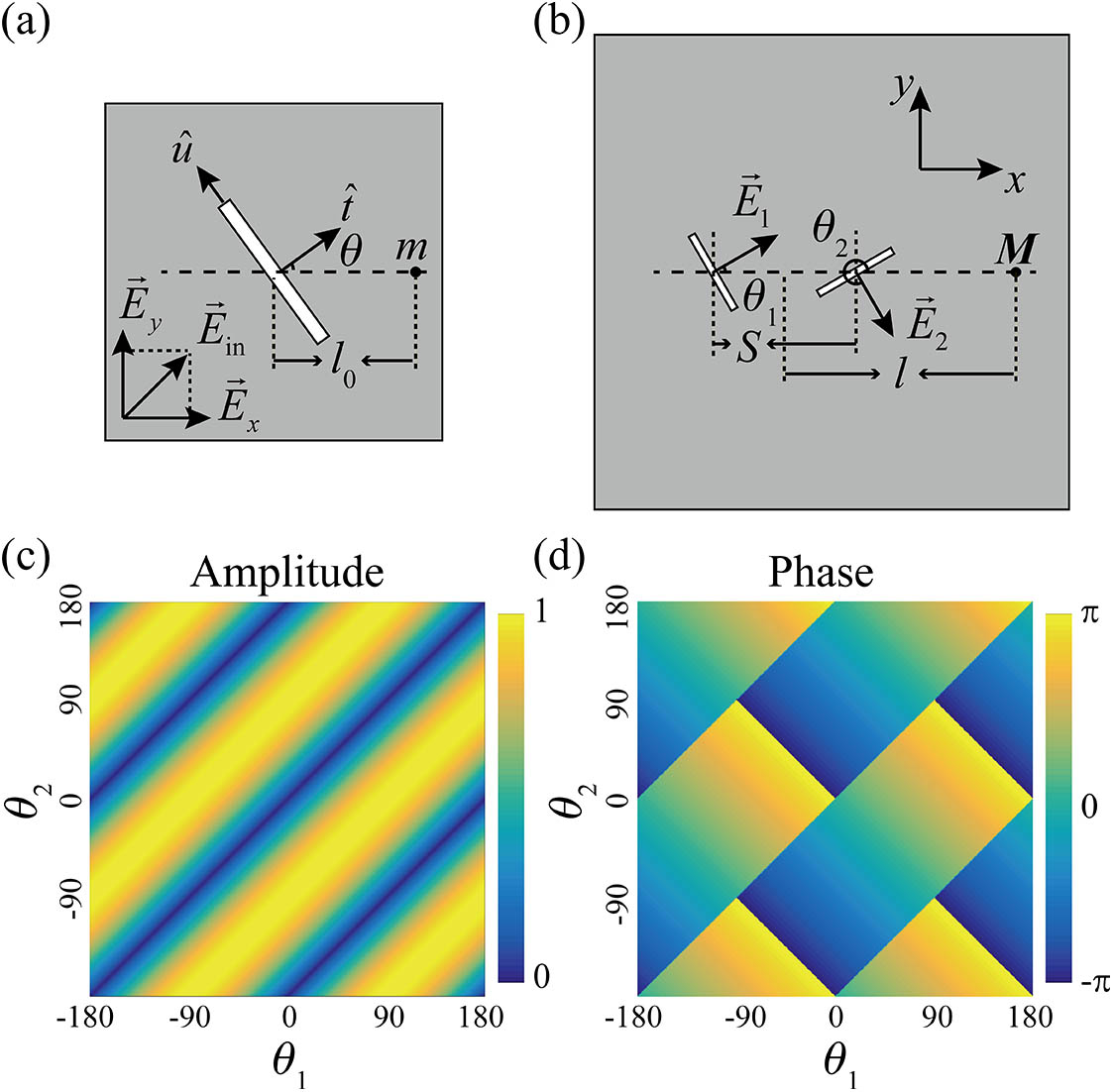
Figure 1(a) illustrates the schematic of a slit resonator made from a metallic film, where represents the incident light, which can be decomposed to and in the basis. For a slit resonator with a large length-to-width ratio, the SWs excited by the component can be neglected[17]. The component, in contrast, can excite the slit resonator at the fundamental resonance and give rise to the excitation of SWs. The resonance mode can be described as
Figure 1.Schematic view of (a) single slit resonator and (b) a pair of slit resonators. (c) Calculated normalized amplitude and (d) phase distributions of the SWs excited by a pair of slit resonators at various and (here, LCP incidence was taken as an example).
Here, is the response of the resonance mode . , , and are the resonance frequency, radiative scattering loss rate, and dissipation loss rate, respectively, and all of these parameters are real. The SW excitation of such a resonance acts as a single in-plane dipole source. Since is dependent on the structure parameters of the slit resonator, the SW excitation of at a certain frequency can be simply defined as , where is the fitting coefficient. By applying a two-dimensional version of the Huygens–Fresnel principle, the SW field at the point can be calculated as where is a unit vector, which represents the direction of the SW electric field, is the SW wave number, is the distance between the slit resonator and point , and represents the angle of with respect to the axis. By carefully designing the locations and orientations using an iterative algorithm[17], holographic principle[21,31], or quasi-crystal configuration[29,33], such slit-resonator-based metasurfaces have shown excellent flexibilities to steer the SWs.
Let us consider a pair of slit resonators separated with a distance with arbitrary angles and , as illustrated in Fig. 1(b), where is the wavelength of the designated SWs. The excited SWs can be calculated as a superposition due to these two slit resonators. If the distance , the amplitude attenuation difference between these two slit resonators can be neglected. In this case, the SW field at point can be calculated as with the coefficient where the incidence is circularly polarized light with representing left-handed circular polarization (LCP) and right-handed circular polarization (RCP), respectively. According to Eq. (3), it is clear that the phase and amplitude of the excited SWs can be freely controlled by the summation and the difference between the angles and , respectively. Figures 1(c) and 1(d) illustrate the relation of the normalized SW amplitude and phase distribution as a function of and under LCP incidence, respectively. Obviously, more than one group of angles could satisfy simultaneous control of the SW amplitude and phase.
By arranging the slit-pair resonators into a column with a linear phase profile, handedness-controlled anomalous terahertz SW launching is observed[27]. Particularly, by using a multi-layer metasurface structure to narrow the bandwidth of the resonance mode , multi-wavelength terahertz SW focusing can thus be achieved[35]. For further complex SW field distribution imaging, due consideration must be given to applying the holographic principle.
The basic principle of holography is the reversibility of the light path. During the past decades, metasurface-based holography has gained enormous interest and achievements in far-field imaging of free-space light[13,14]. In the near-field, however, the SWs emitted from each source will ripple around and interfere with each other, meaning that the propagating and imaging of SWs are in the same platform. Therefore, in order to improve the imaging quality, the target SW pattern should consist of a series of SP point sources with a proper phase gradient that can optimize the interferences[31]. Additionally, in order to record the scattered field information from these point sources as much as possible, a close-loop-shaped hologram ring constituted by slit-pairs is needed, which contains the target pattern inside.
According to Eq. (3), it can be found that the sign of phase distribution is dependent on the handedness . Thus, for the same set of hologram rings, the rebuilt SW pattern would turn to its conjugate version −. Therefore, if a hologram ring is designed as , the rebuilt SP profiles under LCP incidence will be a normal A pattern and a conjugate B profile. In contrast, under RCP incidence it will be a conjugate A pattern and a normal B pattern. In this case, handedness-switched SW holography can be achieved if the conjugate pattern can be diminished. This can be done by multiple hologram rings with a proper radius difference between the neighboring rings. plays a crucial role in diminishing the conjugate patterns and, meanwhile, has nearly no effect on the normal patterns. Figure 2 illustrates the calculated, simulated, and experimental results of a handedness-controlled SW imaging design for rebuilding the - and N-shaped SW patterns under the LCP and RCP incidences, respectively. All of these rebuilt patterns show high imaging quality and less crosstalk.
Figure 2.(a) Calculated, (c) simulated, and (e) measured V-shaped SW intensity profiles () rebuilt under LCP incidence, respectively. (b) Calculated, (d) simulated, and (f) measured N-shaped SW intensity profiles () rebuilt under RCP incidence, respectively. Scale bar: 0.8 mm.
The previous mentioned designs treat each slit resonator as an individual dipole source, and the functionalities were achieved based on the interferences of such sources; meanwhile, the coupling effects among the resonators were purposely excluded or minimized for simplification. Actually, coupling can also be an essential factor in designing the SW excitation. Figure 3(a) illustrates the spectrum of SW excitation of an slit resonator array. As discussed above, by carefully tailoring the geometric parameters, the fundamental resonance of the slit resonators can be excited by polarization and acts as a bright mode at frequency around 0.75 THz. Figure 3(b) illustrates the simulated SW field distribution of the slit resonator array, where SWs can be excited and propagate along the directions. In contrast, the fundamental resonance of a split-ring-shaped slit resonator [SSR, see the inset in Fig. 3(d)] can hardly be directly excited under the -polarization incidence. However, it can couple with the slit resonator, giving rise to a resonance and acting as a dark mode . Note that the second-order resonance of the SSR can be directly excited by the -polarization incidence and give a minor contribution of SW excitation at 0.75 THz, as shown in Figs. 3(c) and 3(d). Here, for simplification, only the SWs excited by the fundamental resonances are considered. The system of a coupled slit-pair resonator [shown as inset in Fig. 3(f)] under the -polarization incidence can be theoretically described by the coupled-mode equations[38]: where is the response of the resonance mode . , , and are the resonance frequency, radiative scattering loss rate, and dissipation loss rate, respectively; is the coupling coefficient between and ; all of these parameters are real. Figures 3(e) and 3(f) illustrate the simulated spectrum and SW field distribution of the coupled slit-pair resonator array, where asymmetric excitation of SWs can be clearly seen, indicating the capability of manipulating SWs by the coupling feature[28].
Figure 3.Simulated spectra and SW field distributions () of (a), (b) slit resonator array, (c), (d) split-ring-shaped slit resonator array, and (e), (f) coupled slit-pair resonator array under the -polarization incidence, respectively. The insets in the top–left corner represent the corresponding unit elements similarly hereinafter. Scale bar: 1 mm.
By simply arranging the location of each coupled slit-pair resonator using the holographic principle, the excited SWs can be steered to form a focusing spot[30]. More intriguingly, from Eq. (5), it can be deduced that the SW excitation of such coupled slit-pair resonators can be tailored by varying the coupling coefficient . It can be done by changing the relative distance between these two element resonators. Figure 4 illustrates the simulated and measured results of a metalens that is constituted by such coupled slit-pair resonators with different vertical distances. It can be seen that the focusing spot in the direction is enhanced as the SSR is gradually moved from the bottom to the top[30].
Figure 4.(a)–(e) Simulated and (f)–(j) measured field intensity distributions () of coupled slit-pair resonator-based metalens with different vertical distances, respectively, under -polarization incidence. Scale bar: 1 mm.
So far, the discussed coupling-induced asymmetric excitation of SWs is only considered under the -polarization incidence. For further complex applications, polarization controllability is highly desired. The recently reported polarization-controlled asymmetric excitation of SWs in metasurfaces has attracted much attention for its promise in developing innovative plasmonic devices. However, most of these works were purposely designed in certain orthogonal polarizations and thus resulted in limited two-level controllability. Here, the properly designed coupled SSR pairs are presented to overcome this limit[34]. As shown in Fig. 5(a), the SSR pair consists of two identical SSRs oriented along the perpendicular directions and is positioned in a mirror-symmetric configuration. Under the -polarization incidence, the top-right SSR () can be directly excited and acts as a bright mode ; meanwhile, the bottom-left SSR () acts as a dark mode . Similarly, under the -polarization incidence, and act as dark mode and bright mode , respectively.
Figure 5.(a) Schematic and (b) sample image of the SSR pair; scale bar: 25 μm. The subscript and superscript of represent the SW propagating direction and SSR number, respectively. (c)–(f) Measured SW field distributions in the case of the -polarized, -polarized, LCP, and RCP incidences, respectively. Scale bar: 1 mm.
Due to the mirror-symmetric configuration, SW excitation under the -polarization incidence will also be mirror symmetric with that under the -polarization incidence. Hence, SW excitation of such an SSR-pair can be seen as a coherent superposition of the - and -polarization excitations. Then, if SW excitation along the direction is weak enough under the -polarization incidence, the SW towards the direction will also be weak under the -polarization incidence. Meanwhile, if the SWs along the and directions under the -polarization incidence have similar amplitudes but a phase difference near , the SWs towards the and directions will be suppressed under RCP and LCP incidences, respectively, due to destructive interference. This can be accomplished by a careful design of the SSR-pairs, since the resonance modes and the coupling coefficient can be manipulated by altering the structural parameters of the SSRs and the distance between these two SSRs, respectively. With the overall performance taken into consideration, the eventually selected and fabricated SSR pair is shown in Fig. 5(b). The corresponding measurements are illustrated in Figs. 5(c)–5(f), where four-level polarization-controlled asymmetric excitation is achieved.
In conclusion, based on near-field scanning terahertz microscopy, several SW manipulation strategies are presented and experimentally demonstrated in the spectrally important terahertz regime. On account of the universalities of the interference and the coupled-mode theory, these design strategies are applicable to a broad electromagnetic spectrum. Particularly, the presented polarization-controlled complex SW field imaging or asymmetric excitation of SWs, in conjunction with dynamic polarization modulation techniques, may open up a gateway towards integrated plasmonic circuitry with electrically reconfigurable functionalities.
References
[1] S. A. Maier. Plasmonics: Fundamentals and Applications(2007).
[13] L. Huang, X. Chen, H. Mühlenbernd, H. Zhang, S. Chen, B. Bai, Q. Tan, G. Jin, K.-W. Cheah, C.-W. Qiu, J. Li, T. Zentgraf, S. Zhang. Nat. Commun., 4, 2808(2013).