Synchronization has great impacts in various fields such as self-clocking, communication, and neural networks. Here, we present a mechanism of synchronization for two mechanical modes in two coupled optomechanical resonators with a parity-time ()-symmetric structure. It is shown that the degree of synchronization between the two far-off-resonant mechanical modes can be increased by decreasing the coupling strength between the two optomechanical resonators due to the large amplification of optomechanical interaction near the exceptional point. Additionally, when we consider the stochastic noises in the optomechanical resonators by working near the exceptional point, we find that more noises can enhance the degree of synchronization of the system under a particular parameter regime. Our results open up a new dimension of research for -symmetric systems and synchronization.
1. INTRODUCTION
Synchronization is a phenomenon in which two or more systems coordinate and act in the same time with similar behaviors. It can be extensively observed in our daily life, such as the chorusing of crickets, flash of fireflies, pendulum clocks, firing neurons, applauding of audiences, and even the life cycle of creatures [1–3]. As synchronization is a qualitative transition where the rhythms of two or more different objects are adjusted in unison, it also attracts great interest and is widely applied to various fields, such as data communication, time keeping, navigation, cryptography, and neuroscience [4–9].
Due to the recent developments of nano-fabrication techniques, especially those for high-quality-factor on-chip optomechanical resonators [10], it is possible to demonstrate synchronization in on-chip nano-scale platforms [11–16]. For example, in Ref. [13], a pair of closely placed optomechanical resonators with different mechanical frequencies was synchronized by indirect coupling through the coupled optical fields. In Ref. [14], two nano-mechanical oscillators separated by about 80 μm were synchronized through the same optical field in an optical racetrack. Moreover, in Ref. [15], master–slave frequency locking was realized between two separated optomechanical oscillators (3.2 km apart) through the light.
Although synchronization in optomechanical resonators has been explored for several years both theoretically and experimentally, there are still several problems left open. One of them is that the frequency mismatch between two synchronized oscillators is required to be very small compared with the inherent frequencies of the two oscillators [12–16]. In the existing experiments [13,15], the frequency differences between the two micro resonators are about dozens of kilohertz (kHz, 70 to 80 kHz), which are far smaller than the natural frequencies [about dozens of megahertz (MHz)] of the two oscillators. In Ref. [12], the authors used the unidirectionally cascaded structure to synchronize two resonators and pointed out that the intrinsic frequency mismatch should be limited to around 1% of the mechanical frequency of the first resonator. In fact, the restriction of intrinsic frequency mismatch between two micro resonators mainly stems from the fact that the vacuum optomechanical coupling strength, i.e., the coupling strength between single photon and single phonon, is traditionally very tiny () [10]. The field-enhanced optomechanical coupling strength is still not strong enough to achieve the strong coupling regime even when it is amplified by the input field [17], which thus results in the limitation of synchronization between micro resonators.
Sign up for Photonics Research TOC. Get the latest issue of Photonics Research delivered right to you!Sign up now
In the past few years, the parity-time ()-symmetric systems, e.g., coupled resonators composed of an active resonator and a passive one, have attracted great attentions [18–27]. In such kind of systems, various interesting properties, such as topological singularity and possible applications, have been studied both theoretically [28–34] and experimentally [35–43]. Especially, in the -symmetric optomechanical systems, in which -symmetric optical modes are coupled to mechanical modes, the optomechanical coupling strength can be greatly enhanced due to the topological singularity at the exceptional point (EP) [29–32].
Motivated by such merits of the -symmetric structure, we study the frequency synchronization in -symmetric optomechanical systems. It is shown that the far-off-resonant mechanical oscillations in two coupled -symmetric optomechanical resonators can be synchronized. Although the optomechanical interaction in our system will influence the EP of the -symmetric structure, this influence is negligibly small under the parameter regime we consider [29–34]. Besides, by introducing the -symmetric structure, we observe an interesting phenomenon, where the two mechanical modes of the coupled optomechanical resonators tend to oscillate in unison by decreasing the optical coupling strength between them. This observation somewhat conflicts with the normal phenomenon where the stronger the coupling strength between two systems is, the easier the synchronization can be realized. Another counterintuitive phenomenon is observed when we consider the noises acting on the optomechanical resonators. It is shown that more noises may benefit the synchronization process between the two mechanical modes.
This paper is organized as follows. In Section 2, we present the -symmetrical optomechanical system we consider. In Section 3, we show how to achieve mechanical frequency synchronization between the two far-off-resonant optomechanical resonators and also analyze the physical mechanism where the frequency synchronization is easier to be realized by decreasing the inter-cavity optical coupling strength. In Section 4, we discuss the positive roles of the optical stochastic noises and the mechanical thermal noises for synchronization, respectively. We summarize our results in Section 5.
2. COUPLED-OPTOMECHANICAL RESONATORS WITH OPTICAL -SYMMETRIC STRUCTURE
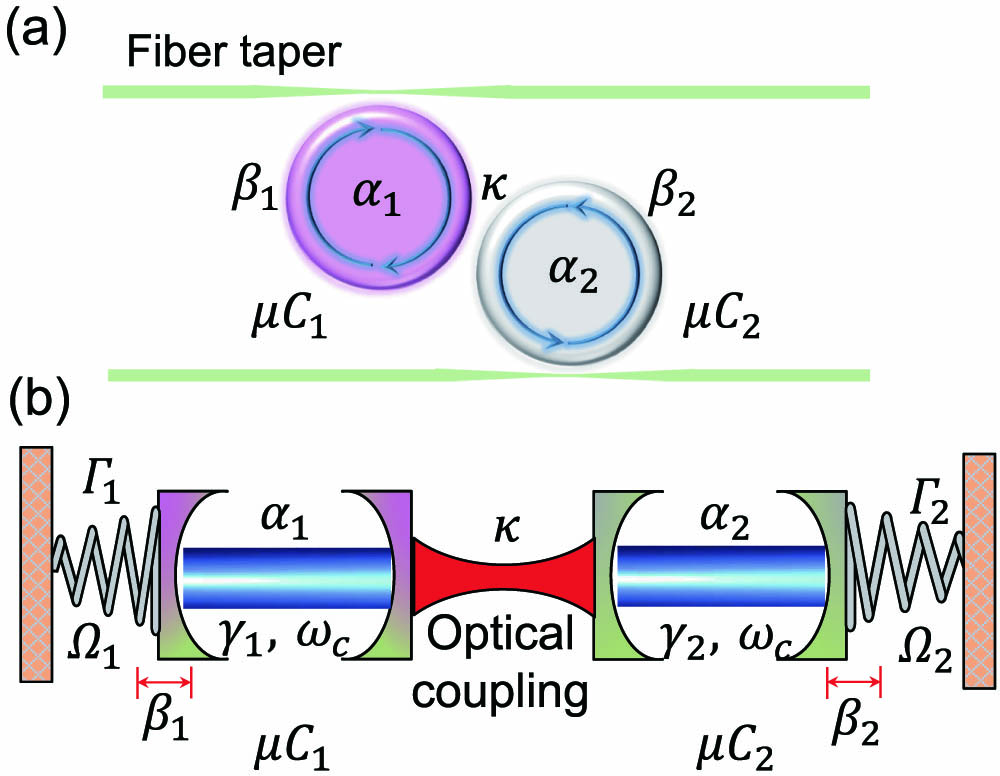
As shown in Fig. 1(a), the system we consider here consists of two coupled whispering-gallery-mode (WGM) resonators. The left WGM resonator () is an active one that can be realized, e.g., by an -doped silica disk, and the right one () is a passive resonator. Each resonator supports an optical mode and a mechanical mode (), and the two resonators are coupled through the inter-cavity evanescent optical fields with coupling strength . As is well known, although the two mechanical modes and , located in two different resonators, are not directly coupled, they can be indirectly coupled through the inter-cavity optical coupling and the intra-cavity optomechanical coupling. We elaborate this indirect mechanical coupling in Fig. 1(b). Each WGM resonator is equivalent to a Fabry–Perot cavity, with one fixed mirror and one movable one. The optical modes and represent the optical fields in the Fabry–Perot cavities, and the mechanical modes and indicate the motions of the movable mirrors. In each equivalent Fabry–Perot cavity, the movable mirror suffers a radiation-pressure force induced by the optical mode (). Such a force is proportional to the circulating optical intensity in the cavity, which leads to the mechanical motion . In the meantime, the movable mirror induces a frequency shift of the optical mode in the cavity, which influences the dynamics of . In Fig. 1(b), () and () interact with each other through this kind of radiation-pressure coupling, and and are directly coupled through the inter-cavity evanescent optical fields and therefore lead to the indirect coupling between mechanical modes and . In other words, these two mechanical modes correspond to optical modes in two different WGM cavities, respectively, and are indirectly coupled with each other through the direct inter-cavity coupling between the corresponding two optical modes.
Figure 1.Schematic diagram of the optically coupled optomechanical system. (a) denotes an active WGM resonator with gain medium, and is a passive one. (b) Equivalent diagram of the optomechanical system, where the WGM resonators are replaced by Fabry–Perot cavities with a movable end mirror and a fixed one. The two cavities are directly coupled through the inter-cavity evanescent optical fields, and the optical coupling strength depends on the distance between the two Fabry–Perot cavities.
The -symmetric optomechanical system we consider can be represented by the following equations: where and . , , , and () denote the gain (loss) rate of the resonator , the external damping rate induced by the coupling between the resonator and the input/output fiber taper, the detuning frequency between the resonance frequency () of the cavity mode and the frequency () of the driving field, and the amplitude of the driving field, respectively. and represent the frequency and damping rate of the mechanical mode . is the vacuum optomechanical coupling strength. Without loss of generality, here we assume that . To simplify our discussion, we assume that the gain cavity and the lossy cavity have the same vacuum optomechanical coupling strength . We also assume that the gain and loss in the system are well balanced, i.e., . Additionally, we consider the case of critical coupling such that , under which a phase transition point exists called the EP, corresponding to a critical inter-cavity coupling strength . When , which is in so-called -symmetric regime, two non-degenerate optical supermodes exist with the same damping rate. When , which is in the so-called broken -symmetric regime, the two optical supermodes are degenerate but with different damping rates. When the system is far away from the EP, the interaction between the optical supermodes and mechanical modes, i.e., the effective radiation-pressure coupling in the supermode picture, is weak. However, this kind of interaction will be greatly enhanced as gets closer to . This comes from the topological-singularity-induced amplification of the optomechanical nonlinearity in the vicinity of the EP [29–32].
Slightly different from Refs. [29–33], in this work, we assume that the difference between the frequency detunings and is non-zero, i.e., . This non-zero difference between the frequency detunings can eliminate the degeneracy of the optical supermodes at the EP and thus affect the -symmetric structure in our system. Therefore, in this work, we need to emphasize that the difference between the two frequency detunings should be small, such that the non-degeneracy of the optical supermodes at EP is very small, and the -symmetric structure of the optical modes is still maintained. In fact, by eliminating the mechanical modes in Eq. (1), the dynamics of the two optical modes can be given by where , and and are the optical frequency shifts induced by the optomechanical interaction (for details see Appendix A). By diagonalizing the coefficient matrix in Eq. (2), we can obtain two optical supermodes , where the corresponding eigenfrequencies can be given by
Since is very small compared with the frequency detuning , the eigenfrequencies of the two optical supermodes can be reduced to
It can be shown in Eq. (4) that both optical supermodes will be degenerate at the EP () if . However, if is non-zero, the degeneracy between these two supermodes will be eliminated.
Then, let us assume that and the two optical driving fields have the same amplitude, i.e., . In this case, this non-degeneracy between the two supermodes at the point can be evaluated as follows: where . The non-degeneracy described in Eq. (6) can be simplified further as under the condition , which means that this non-degeneracy is negligibly small when is small enough. Given the system parameters , , , , , , , , and , the simulation results of the mode splitting and linewidth of the optical supermodes are shown in Figs. 2(a) and 2(b), respectively. The simulation results of the non-degeneracy at the EP in Fig. 2 are around 6 MHz. It is obvious that this non-degeneracy at the EP is negligibly small compared with the optical damping rate , and the broken--symmetric and -symmetric regimes can be clearly observed, as illustrated in Fig. 2. It should be noted that although one eigenfrequency of the optical supermodes has a positive imaginary part, which corresponds to a positive damping rate in the broken--symmetric regime [Fig. 2(b)], the saturation nonlinearity induced by the optomechanical coupling will suppress the divergence induced by this positive damping rate [44,45]. It also should be noted that the non-zero difference between the frequency detunings can break the -symmetric optical structure by lifting the degeneracy between the optical supermodes. However, as is so small, i.e., , where the non-degeneracy between optical supermodes is negligibly small, the properties of the -symmetric structure, including the mode-splitting of the supermodes [Fig. 2(a)] and the great amplification of optomechanical interaction mentioned in the later discussion, are maintained. Thus, we still name our system in this paper as a -symmetric optomechanical system in accord with previous literatures [29–33].
Figure 2.(a) Mode splitting of the supermodes, i.e., the real parts of the eigenfrequencies and (b) linewidth of the supermodes, i.e., the imaginary parts of the eigenfrequencies. The green region is the broken--symmetry regime, and the pink region corresponds to the -symmetry regime.
In order to elaborate how the enhancement of the optomechanical interaction in the vicinity of the EP affects the synchronization between the two mechanical modes, we adiabatically eliminate the degrees of freedom of the optical modes. This enhanced optomechanical coupling will induce significant optomechanics-induced frequency shifts and for the mechanical modes and . In fact, under the condition that , and , and near the EP can be given by (for detailed derivation see Appendix B)
We show in Fig. 3(a) the optomechanics-induced mechanical frequency shifts (red-solid curve) and (blue-dashed curve) of the two resonators versus the optical coupling strength , both in broken--symmetric and -symmetric regimes. When the system is far away from the EP, the optomechanics-induced mechanical frequency shift is negligibly small. However, will be greatly enhanced such that is almost comparable with or even larger than when approaches . As these two enhanced frequency shifts for the mechanical modes are opposite in sign, they will lead to significant modifications of mechanical frequencies and and make the two mechanical frequencies and approach each other.
Figure 3.(a) Optomechanics-induced mechanical frequency shifts of the two optomechanical resonators versus the optical coupling strength both in the broken--symmetric regime and the -symmetric regime. (b) Effective coupling strength between two mechanical modes versus the optical coupling strength .
Moreover, in the vicinity of the EP, this enhanced optomechanical coupling can also induce an enhancement of the effective mechanical coupling strength between the mechanical modes and . Similarly, by adiabatically eliminating the degrees of freedom of the optical modes, this effective coupling strength between the two mechanical modes and can be expressed as
In Fig. 3(b), the effective mechanical coupling strength versus the optical coupling strength is plotted both in broken--symmetric and -symmetric regimes. It can be clearly seen that the effective mechanical coupling strength is very tiny when the system is far away from the EP, but it can be significantly enhanced when approaches . This enhanced effective mechanical interaction in the vicinity of the EP can also contribute to the synchronization between the two mechanical modes and .
Actually, the effective mechanical frequencies of the two mechanical oscillators can be expressed as and , respectively, where comes from the effective mechanical coupling strength (see Appendix D). This means that the enhanced optomechanics-induced mechanical frequency shifts and effective mechanical coupling strength can lead to significant modifications of mechanical frequencies together and thus jointly contribute to the synchronization between the two mechanical oscillators, i.e., . We show in Fig. 4(a) the effective mechanical frequencies (red-solid curve) and (blue-dashed curve) of the two resonators versus the optical coupling strength , both in broken--symmetric and -symmetric regimes. It is clear that the two mechanical oscillators tend to be resonant with each other, i.e., , and thus synchronize when approaches . As is well known, the frequency mismatch between two synchronized oscillators should be very small in traditional lossy systems [12,13], i.e., . However, as shown in Fig. 4, our -symmetric system can perfectly synchronize two far-off-resonant mechanical oscillators. Actually, as shown in Fig. 4(a), where the nature frequencies and , the effective mechanical frequencies and of the two optomechanical resonators coincide with each other when approaches , even when the nature frequency mismatch (10 MHz) is comparable with the nature frequencies of the two mechanical oscillators, i.e., . The oscillators with such large frequency mismatch cannot be synchronized in the traditional lossy systems [12,13].
Figure 4.(a) Effective mechanical frequencies and versus the optical coupling strength , where the red solid (blue dashed) curve represents the frequency of () and the light green (pink) area is the broken--symmetric (-symmetric) regime. (b) Numerical results of cross-correlation with different values of in broken--symmetric and -symmetric regimes. (c) Spectrograms of mechanical modes and with increasing optical coupling strength in the broken--symmetric regime, where the nature frequencies of are 5 MHz and 15 MHz, respectively. Here, () denotes the increasing (decreasing) of from 2 MHz and 29.86 MHz (50 MHz to 30.81 MHz), and the left and right red arrows indicate the moving direction of the spectra of and by increasing (decreasing) , as shown in (c) [(d)]. (d) Spectrograms of mechanical modes and with decreasing optical coupling strength in the -symmetric regime, in which weaker coupling strength makes the two resonators more easily be synchronized.
In addition, we find a counterintuitive phenomenon, where weaker coupling between two optomechanical resonators may be helpful for synchronization for our optomechanical system. In fact, as shown in Fig. 4(a), in the -symmetric regime (the pink region), when the coupling strength between two resonators is decreased, the effective mechanical frequencies of the two resonators tend to coincide with each other, which means that and are inclined to oscillate in unison with the weaker coupling strength in the -symmetric regime. The broken--symmetric regime is the normal regime where stronger coupling between the two optomechanical resonators makes the two mechanical modes and be inclined to be synchronized. We can more easily see this phenomenon by plotting the spectra of the normalized mechanical displacements of the two optomechanical resonators (the red solid curve) and (the blue dashed curve) in Figs. 4(c) and 4(d), where is increased from 2 MHz to 29.86 MHz in Fig. 4(c) and is decreased from 50 MHz to 30.81 MHz in Fig. 4(d). In Figs. 4(c) and 4(d), the red solid and blue dashed Lorentz peaks represent the spectra of and , respectively. The left and right red arrows, as shown in Fig. 4(c) [Fig. 4(d)], separately denote the moving direction of spectra of and by increasing (decreasing) the optical coupling strength . The left red solid and right dashed peaks are located at the nature frequencies of (5 MHz) and (15 MHz) when (2 MHz) is far away from the EP (), and approach each other and overlap in the middle position at 10.51 MHz while is increased to 29.86 MHz, as shown in Fig. 4(c). In other words, with the increase of the inter-cavity coupling strength in the broken--symmetric regime, the Lorentz spectra of and get closer and finally coincide with each other, which means that the two mechanical modes are resonant. However, contrary to our intuition, the resonant peaks of and get closer by decreasing in the -symmetric regime, as shown in Fig. 2(d). This counterintuitive phenomenon stems from the fact that synchronization only takes place when we approach the EP for two far-off-resonant mechanical modes. In fact, as shown in Eqs. (7) and (8), the optomechanically induced mechanical frequency shifts and effective mechanical coupling strength depend not only on the optical coupling strength but also on the optomechanical coupling strength. When we approach EP in the -symmetric regime, the effective optomechanical coupling strength will be greatly enhanced due to the topological-singularity-induced amplification of optomechanical nonlinearity in the vicinity of the EP [29–34], although the optical coupling strength decreases. The increase of the effective optomechanical coupling strength compensates the decrease of the inter-cavity optical coupling strength and thus results in the enhancement of optomechanically induced mechanical frequency shifts and effective mechanical coupling strength simultaneously, which finally induces the large modification of the effective mechanical frequencies of the two resonators. This is the mechanism where weak coupling strength is not detrimental to synchronization, but benefits to it in the -symmetric regime.
To give more insights into the phenomena shown, we plot in Fig. 4(b) the cross-correlation function between the two mechanical displacements and with different inter-cavity optical coupling strength , where is defined as [46–52]
This normalized cross-correlation function varies between 0 and 1. The maximum value of indicates that the two time series of the mechanical displacements and have exactly the same shape, even though their amplitudes may be different, which implies that the two self-sustained oscillators have the same frequency, that is, the onset of synchronization. As shown in Fig. 4(b), in the -symmetric regime, smaller induces higher value of (the red solid curve), and reaches the maximum value (the unit) as decreases and approaches EP, which means that the two mechanical displacements and tend to be synchronized with the decrease of the inter-cavity coupling strength. However, in the broken--symmetric regime, the cross-correlation function [the blue dashed curve in Fig. 4(b)] increases and tends to unit with the increase of , which means that stronger inter-cavity coupling strength will be helpful for synchronization as expected.
4. NOISE-ENHANCED SYNCHRONIZATION IN -SYMMETRIC OPTOMECHANICAL SYSTEM
A. Stochastic Noises in the Optical Modes
We now study the effects of the stochastic noises on our -symmetric optomechanical system. Two independently identically distributed Gaussian white noises are introduced for the two optical modes , such that , where is the intensity of the noises and small to protect the -symmetric structure. Here, we have included the shifts of damping rates induced by stochastic noises into the gain () and loss () rates in our optomechanical system. Thus, the dynamical equations of our -symmetric system can be reexpressed as where .
We present the numerical results of the cross-correlation function between the two mechanical oscillators in Figs. 5(a) and 5(c) by changing the noise strength and fixing other parameters both in broken--symmetric and -symmetric regimes. In order to show the benefit to the synchronization better, we choose the optical coupling strength as in the broken--symmetric regime, since the enhancement of the degree of synchronization induced by noises is large at this coupling strength when other system parameters are fixed, as shown in Figs. 5(a) and 5(b). Similarly, in Figs. 5(c) and 5(d), we choose in the -symmetric regime to exhibit advantages of noises for synchronization. It can be seen that is enhanced with increasing noise intensity both in broken--symmetric and -symmetric regimes, reaches the maximal values at particular noise level, and then decreases at higher noise intensity. It means that synchronization process may benefit from noises [53–60] in our optomechanical -symmetric system if the strength of the noise is not too large. To interpret what we observe, we can see that the noises will randomly shift the frequencies of the mechanical modes, especially when we approach the EP where the effects of noises are enhanced [61–64]. Since the frequencies of the two mechanical modes are far-separated, these random frequency shifts may decrease the difference between the frequencies of the two mechanical modes in a certain probability with increasing noise strength and thus increase the cross-correlation function . When we increase the noise strength further, the noise will be strong enough to destroy the periodic oscillation of a single mechanical oscillator and the -symmetric structure of the optomechanical system and thus decrease the degree of synchronization between the two mechanical oscillators. This interpretation can also be confirmed by checking the variance of versus the noise strength [Figs. 5(b) and 5(d)]. The variance of first increases with increasing noise strength (note that increases at the same time), which means that more noises enter the system although is increased. The variance of then decreases when we increase further, because the value of is small in this case, and the noise-induced fluctuations in are suppressed. This is the essential reason why stochastic noises at moderate levels can benefit synchronization in the -symmetric optomechanical system.
Figure 5.(a) Effects of the stochastic noises on with respect to different stochastic noise intensity in the broken--symmetric regime with . (b) Variances of versus noise level in (a). (c) Effects of the stochastic noises on versus different in the -symmetric regime with . The variance of is presented in (d).
We also check another index of synchronization, the Kramers rate, which is an alternative index to show the correlation between the two subsystems and suitable to describe noisy synchronized systems. When the Kramers rates of two subsystems coincide with each other, the two subsystems are well correlated [53]. Now, we calculate the Kramers rates and of the mechanical displacements and , respectively. The Kramers rate is originally defined as the transition rate between neighboring potential wells of a particle caused by stochastic forces, which was first proposed by Kramers in 1940 [65].
Here, we use the mean first passage time [66,67], i.e., the average time that the particle moves from one potential well to the other well, to evaluate the Kramers rates and of mechanical displacements and . We obtain the histograms of through numerical simulation first, then search for the locations with the maximum probability of , i.e., the bottoms of the potential wells of , based on the distribution of histograms, and finally calculate the mean first passage times , i.e., the average times of jumps between the two potential wells for each mechanical displacement. The Kramers rates and can then be calculated by the reciprocal of the mean first passage times , i.e., (). The simulation results for and are presented in Fig. 6. It can be seen that the Kramers rates and get closer with the increase of the noise intensity in both broken--symmetric [Fig. 6(a)] and -symmetric [Fig. 6(b)] regimes, which indicates that the frequencies of the mechanical displacements and get closer when the noise intensity increases.
Figure 6.Kramers rates and of mechanical displacements and versus the noise intensity in broken--symmetric and -symmetric regimes. (a) The red curve (blue curve) represents the curve for Kramers rate () versus the noise intensity in the broken--symmetric regime. Here, the optical coupling strength is fixed. (b) The simulation results of Kramers rates and versus noise intensity in the -symmetric regime, where the optical coupling strength is fixed as .
In the above analysis, we do not consider the effects of the thermal noises of the mechanical modes on synchronization. However, these thermal noises acting on the mechanical modes can also benefit the synchronization between the two mechanical modes in our -symmetric optomechanical system. In order to simplify the discussions, we only consider the thermal noises in the mechanical modes and do not exert extra stochastic noises to the optical modes in this subsection, and we assume that these thermal noises are white noises, based on which the Langevin equations of the mechanical modes can be expressed as where the constant driving terms induced by the optical modes have been included into by a coordinate transformation. The mechanical damping rate consists of the original mechanical damping rate and the noise-induced damping rate , i.e., . The mechanical thermal noises and are diffusion terms with -correlated Gaussian distribution, where is the Boltzman’s constant, and is the temperature.
To show the beneficial effect of thermal noises on synchronization, we present the numerical results of the normalized correlation function [68] between the two mechanical oscillators in Figs. 7(a) and 7(b) by changing the temperature and fixing other parameters in both broken--symmetric and -symmetric regimes, where is the room temperature. In the broken--symmetric regime with fixed , (blue-dashed curve) increases with increasing temperature and reaches 0.61 at the room temperature , which is larger than 0.48 when we disregard the thermal noises. Similarly, in the -symmetric regime with fixed , (red-solid curve) increases with increasing temperature and reaches 0.65 at room temperature, which is larger than 0.51 when we omit the thermal noises. It means that the thermal noises in the mechanical modes can also benefit the synchronization between the two mechanical modes in our optomechanical -symmetric system.
Figure 7.Numerical results of the normalized correlation function with different values of temperature in broken--symmetric and -symmetric regimes, where denotes the room temperature. (a) Effects of the thermal noises on with respect to different temperature in the broken--symmetric regime with . (b) Effects of the thermal noises on versus in the -symmetric regime with .
To give more insights into the phenomenon presented, we calculate the Kramers rates and of mechanical displacements and . The simulation results for Kramers rates and are illustrated in Fig. 8. In Fig. 8(a), the red (blue) curve denotes Kramers rate () with different values of temperature in the broken--symmetric regime, where optical coupling strength is . We can see in Fig. 8(a) that Kramers rates and tend to get closer to each other as the temperature increases to the room temperature . A similar phenomenon can be observed in the -symmetric regime, as shown in Fig. 8(b), i.e., the mechanical thermal noises tend to decrease the difference between the Kramers rates and as the temperature increases to room temperature, where the optical coupling strength is fixed as . These simulation results indicate that mechanical thermal noises can make the frequencies of the two mechanical displacements and tend to be consistent with each other and thus benefit the synchronization in our -symmetric optommechanical system.
Figure 8.Kramers rates and of the mechanical displacements and versus the temperature in both broken--symmetric and -symmetric regimes, where is the room temperature. (a) The red curve (blue curve) denotes the Kramers rate () with increasing temperature in the broken--symmetric regime, where the optical coupling strength is fixed. (b) The Kramers rates and versus the temperature correspond to the -symmetric regime ().
Furthermore, we can also observe the beneficial effect of the mechanical thermal noises on the synchronization by theoretically analyzing the correlation function between the two mechanical modes. Actually, at small time limit [68], the normalized correlation function between the two mechanical modes can be approximately calculated by (derivation, see Appendix G) where is the intensity of the mechanical thermal noises. It is shown in Eq. (13) that the normalized correlation function can be enhanced by increasing the intensity of the thermal noises, which is consistent with the above simulation results, as shown in Figs. 7 and 8.
5. CONCLUSIONS
We have shown that the mechanical motions of two coupled -symmetric optomechanical resonators with far-off-resonant mechanical frequencies can be synchronized when the system approaches the EP. In particular, in the -symmetric regime, the two mechanical modes are easier to be synchronized with weaker optical coupling strength between the two optomechanical resonators. Additionally, it is shown that noises will be enhanced in the vicinity of the EP in our system, and the enhanced noises will benefit the synchronization process if only the strengths of the noises are not too strong. Our study opens up a new dimension of research for -symmetric optomechanical systems for possible applications such as metrology, cooling, and communication. It also gives new perspectives for synchronization in optomechanical systems.
APPENDIX A: PT-SYMMETRIC OPTOMECHANICAL SYSTEM WITH Δ?=|Δ2?Δ1|?Δ1,Δ2
Generally, in our optomechanical system, if we consider symmetric optical frequency detunings , an EP exists, where the two optical supermodes degenerate with each other at this point. However, if , the degeneracy of the optical supermodes at the previous EP will be broken. Now, we demonstrate that if is appropriately chosen, this non-degeneracy will be small, and the properties of the -symmetric structure will be maintained in our -symmetric optomechanical system.
In order to analyze the -symmetric structure in our optomechanical system, we only consider the optical modes and assume that the nonlinear optomechanical interaction between the optical mode and mechanical mode only leads to an optomechanics-induced frequency shift for the corresponding optical mode in each cavity [32]. Here, we treat the stationary state () of the mechanical mode () as a parameter that leads to a frequency detuning [] for the optical mode (). By taking in Eq. (1), we can obtain the stationary states of the optical and mechanical modes, which satisfy the following equations:
By solving the above equations, the stationary states of the mechanical modes can be expressed as and the stationary states of the optical modes satisfy the following equations: where
By substituting the stationary states and into Eq. (1) and eliminating the mechanical modes, we obtain the reduced motion equations of the two coupled optical modes as follows:
Based on Eq. (A5), we can calculate the eigenfrequencies of the optical supermodes as where and . Considering the balanced gain and loss (), the above equation can be reduced to
Actually, the vacuum optomechanical coupling in traditional microresonators [10] is very small, which means that and are very tiny; thus, if is small enough, the imaginary parts in the root signs in Eq. (A7) can be omitted, and the eigenvalues can be approximately reduced to
It means that the two eigenvalues of optical supermodes tend to degenerate with each other at the EP () when is small enough. In fact, in order to approximately evaluate stationary states and , we can neglect and in Eq. (A3) and thus obtain and , since and are far smaller than and . By substituting and into Eqs. (A4) and (A7), the non-degeneracy of the optical supermodes at the EP () can be approximately expressed as under the condition where . Equation (A9) can also be further simplified to under the condition . It can be inferred that this non-degeneracy will be small, and the properties of the -symmetric structure will be maintained in our optomechanical system if the value of is appropriately chosen between and .
As for the simulation results in Figs. 2(a) and 2(b) in the main text, we first calculate the stationary states of and by numerically solving Eq. (A3) and then obtain the eigenvalues of the optical supermodes by substituting and into Eqs. (A4) and (A7).
APPENDIX B: THE DERIVATION OF THE REDUCED DYNAMICAL EQUATIONS OF THE MECHANICAL MODES
Based on dynamical Eq. (1), we can adiabatically eliminate the degrees of freedom of the optical modes under the condition that the optical decay rates are far larger than the mechanical decay rates and derive the reduced dynamical equations of the mechanical modes. In fact, by rewriting the first two equations in Eq. (1) in matrix format, we have where
The matrix can be diagonalized as where and where and . Thus, we can introduce the following optical supermodes: by which Eq. (B1) can be re-expressed as where and
To adiabatically eliminate the degrees of freedom of the optical modes, we let , by which we can obtain the following stationary solution: where
By introducing the power-series expansion and omitting high-order terms of and since , the above solutions can be simplified as where
Thus, the stationary solutions of and can be expressed as where and
By substituting the above stationary solutions and into the dynamical equations of the mechanical modes and in Eq. (1), and dropping the counter-rotating terms with , the dynamical equations of the reduced mechanical system can be expressed in the matrix format as where where .
APPENDIX C: THE OPTOMECHANICS-INDUCED MECHANICAL FREQUENCY SHIFTS AND EFFECTIVE MECHANICAL COUPLING
In our -symmetric system, we consider well-balanced gain and loss such that and also consider the critical coupling case such that . When and , the two mechanical frequency shifts in Eq. (B7) can be simplified as
We show the optomechanics-induced mechanical frequency shifts in Fig. 9(a). When the system is far away from the EP, the mechanical frequency shifts (red solid line) and (red dashed line) are negligibly small in comparison with the mechanical frequencies . However, both frequency shifts and will be greatly amplified in the vicinity of the EP, which will modify the mechanical frequencies such that the frequencies of the mechanical modes tend to overlap. As shown in Fig. 9(a), in the -symmetric regime (pink area) of the optical modes, these mechanical frequency shifts are enhanced with the decrease of the optical coupling strength , which means that smaller coupling strength between two optical modes is better for synchronization. In addition, as shown in Fig. 9(a), the difference between the detuning frequencies of the two optical modes, i.e., , significantly influences the amplification of the mechanical frequency shifts when the system is around the EP. By fixing , we plot the curves of for different . We can see that the mechanical frequency shifts are greatly enhanced with the decrease of in the vicinity of the EP.
Figure 9.(a) Optomechanics-induced mechanical frequency shifts versus the optical coupling strength in the broken--symmetric regime (light green area) and -symmetric regime (pink area). Here, we fix and plot the curves of for different . The solid (dashed) curves denote the curves of the mechanical frequency shift () with different . (b) The effective mechanical coupling strength between the two mechanical modes versus the optical coupling strength .
Under the same assumptions, the strength of the effective mechanical coupling in Eq. (B7) can be simplified as and thus the effective mechanical coupling will be greatly amplified in the vicinity of the EP. We then plot the curves of the effective mechanical coupling strength versus the optical coupling strength in Fig. 9(b). Here, we also fix and tune the detuning frequency . It can be seen that the effective mechanical coupling strength is significantly enhanced in the vicinity of the EP. Therefore, in the -symmetric regime, weaker optical coupling strength leads to stronger effective mechanical coupling strength and thus may be helpful for the synchronization between the two mechanical modes. It is also shown that the degree of amplification of is extensively enhanced with the decreasing of in the vicinity of the EP.
APPENDIX D: THE INFLUENCE OF THE EFFECTIVE MECHANICAL COUPLING STRENGTH ON SYNCHRONIZATION
In this part, we discuss the positive effect of the enhancement of the effective mechanical coupling on the synchronization between mechanical modes, i.e., the stronger the is, the easier the synchronization is. For simplicity and clarity, we re-express the dynamical equation in Eq. (B6) by using the differential operator format as follows: where represents the differential operator. By eliminating the degree of freedom of , we can derive the dynamical equation of and then obtain the characteristic equation of this coupled system as follows:
By considering , the roots of this characteristic equation can be expressed as where
It can be easily seen that in the weak coupling regime such that , the vibration frequencies of the mechanical modes get closer to each other with the increase of the effective coupling strength , which means that the degree of synchronization between the two mechanical modes increases with increasing . At the critical point such that , the two oscillators will have the same vibration frequency , which means that the frequency synchronization between the two mechanical modes is accomplished, i.e., the frequencies of the two mechanical modes are equal to each other. It is shown that a stronger effective mechanical coupling strength can improve the degree of synchronization between the mechanical modes in our system and thus leads to frequency synchronization when the effective mechanical coupling is strong enough.
In addition, in the weak coupling regime, Eq. (D1) can also be re-expressed as where and is induced by the effective mechanical coupling strength . In other words, the effective frequencies of the two mechanical modes can be given by where () is the effective frequency of mechanical mode (). It can be seen in Eq. (D4) that both optomechanics-induced mechanical frequency shift and effective mechanical coupling can result in frequency shifts for the two mechanical modes and thus contribute to the synchronization together.
APPENDIX E: THE ENHANCEMENT OF THE OPTOMECHANICAL INTERACTION IN PT-SYMMETRIC OPTOMECHANICAL SYSTEM
In our -symmetric optomechanical system, an enhancement of the effective optomechanical coupling due to the topological-singularity-induced amplification of optomechanical nonlinearity in the vicinity of the EP exists [29,64]. This enhanced optomechanical coupling then leads to the amplification of the optomechanics-induced mechanical frequency shifts and the effective mechanical coupling strength . Since both the optomechanics-induced mechanical frequency shifts and the effective mechanical coupling can change the frequencies of the two mechanical modes, the synchronization between far-off-resonant mechanical modes may be realized with sufficiently large optomechanical coupling strength. In the -symmetric regime, the system gets close to the EP with the decrease of the optical coupling strength , which results in an enhancement of the optomechanical coupling and thus compensates the reduction of the inter-cavity optical coupling strength. In the following part of this subsection, we will show that the optomechanical coupling can be largely enhanced in our -symmetric system.
In our optomechanical system, the interaction Hamiltonian between optical modes and mechanical modes can be expressed as where () and () represent the annihilation operators of the optical mode and mechanical mode in the active (passive) resonator, respectively, and is the vacuum optomechanical coupling strength. If we re-write this interaction Hamiltonian in the optical supermodes picture, then the effective optomechanical coupling strength between optical supermodes and mechanical modes can be expressed as
Since , the effective optomechanical coupling strength can be greatly amplified in the vicinity of the EP when . We show the simulation results of the effective optomechanical coupling strength versus the optical coupling strength in Fig. 10. When the optical coupling strength is far away from the EP, i.e., in the green areas in Fig. 10, the effective optomechanical coupling strength changes slowly with the optical coupling strength . However, in the pink area, increases very fast when the system approaches the EP. In addition, by comparing Eq. (E2) with Eqs. (C1) and (C2), we can find that and , which means that the enhanced optomechanical coupling strength can lead to improvements of the optomechanics-induced mechanical frequency shifts and the effective mechanical coupling in the vicinity of the EP. It should be pointed out that the optical spring effect, i.e., the mechanical frequency shift induced by the optical field, can be increased in the strong optomechanical coupling regime, which is beneficial to the synchronization between two mechanical resonators. However, in our scheme, as the effective optomechanical coupling strength can be greatly enhanced due to the topological-singularity-induced amplification of the -symmetric structure, we do not require the strict condition of strong coupling regime in our scheme, which minimizes the restrictions on synchronization in experiment.
Figure 10.Effective optomechanical coupling strength versus the optical coupling strength . In the green area, the system is far away from the EP, and the effective optomechanical coupling strength is linearly dependent on . In the pink area, the system is in the vicinity of the EP, and, in this case, changes nonlinearly with .
APPENDIX F: THE DIFFERENCE BETWEEN ACTIVE PT-SYMMETRIC SYSTEM AND PASSIVE SYSTEM WITH EP FOR SYNCHRONIZATION
Based on the previous discussion, we know that in the discussed gain–loss balanced -symmetric optomechanical system there exists amplifications of the optomechanics-induced mechanical frequency shifts and effective mechanical coupling strength in the vicinity of the EP. However, if this -symmetric system is replaced by a passive coupled system with an EP, i.e., the active resonator in the discussed -symmetric system is replaced by a passive resonator, the two far-detuned mechanical modes in this system will not be synchronized. To show this, we can easily obtain the dynamical equations of the system by replacing the optical damping in Eq. (1) with as follows:
Under the assumptions that and , the optomechanics-induced mechanical frequency shifts and the effective mechanical coupling can be approximately expressed as where and . As , and is very tiny, and are very small. This implies that in this passive system with an EP, the amplifications of mechanical frequency shifts and effective mechanical coupling are not strong enough. Thus, these two mechanical modes with far-off-resonant mechanical frequencies cannot be synchronized.
In addition, if the balance between gain and loss is broken in our -symmetric system, i.e., , the synchronization between the two mechanical modes will be suppressed. In fact, when the balance between gain and loss is broken, the mechanical frequency shifts and the effective mechanical coupling can be expressed as
Therefore, with the increase of , the amplification effects of the mechanical frequency shifts and the effective mechanical coupling strength will be suppressed. We show the mechanical frequency shifts and the effective mechanical coupling strength with different in Figs. 11(a), 11(b), and 11(c), respectively. It can be clearly seen that the amplifications of the mechanical frequency shifts and the effective mechanical coupling strength are seriously suppressed when is large; thus, the synchronization between the two mechanical modes with far-off resonance is difficult.
Figure 11.(a) Optomechanics-induced mechanical frequency shifts versus the optical coupling strength with different . The solid curve denotes the case where gain and loss are balanced, i.e., . It is shown that the amplification effects of are suppressed with the increase of . (b) Corresponding optomechanics-induced mechanical frequency shifts versus the optical coupling strength with different . (c) Effective mechanical coupling between the two mechanical modes versus the optical coupling strength with different . It is shown that the amplification of is also suppressed with the increase of .
APPENDIX G: NORMALIZED CORRELATION FUNCTION IN PT-SYMMETRIC OPTOMECHANICAL SYSTEM WITH THERMAL NOISES
In this subsection, we will discuss the influence of the thermal noises in mechanical modes on the normalized correlation function between the two mechanical modes. To simplify our discussions, we redefine four variables, thus, the Langevin equation of the mechanical modes in Eq. (7) in the main text can be re-expressed as where , , and . The solution of the above matrix equation can be expressed as where matrix , and represents the initial values of the variables . As we consider small time , the matrix can be approximately expressed as thus, the solution of in Eq. (G3) can be approximately expressed as
Similarly, other solutions in Eq. (G3) can be approximately expressed as
We then calculate the correlation functions as where is the ensemble average over the stochastic noises. Based on the regression theorem [68], we know that the correlation functions can be reduced to
By substituting the solutions of , as shown in Eqs. (G7) and (G8), into the correlation functions [Eq. (G9)], the three correlation functions , , and can be expressed as
For simplicity, we assume that the system is stationary at the initial time, i.e., and consider the case where ; thus, the normalized correlation function between the two mechanical modes can be approximately expressed as
References
[1] A. S. Pikovsky, M. Rosenblum, J. Kurths. Synchronization: A Unified Approach to Nolinear Science(2001).
[2] R. Brown, L. Kocarev. A unifying definition of synchronization for dynamical systems. Chaos, 10, 344-349(2000).
[3] L. Glass, M. C. Mackey. From Clocks to Chaos: The Rhythms of Life(1988).
[4] A. T. Winfree. The Geometry of Biological Time(2001).
[5] A. Goldbeter. Biochemical Oscillations and Cellular Rhythms: The Molecular Bases of Periodic and Chaotic Behaviour(1996).
[6] A. F. Taylor, M. R. Tinsley, F. Wang, Z. Y. Huang, K. Showalter. Dynamical quorum sensing and synchronization in large populations of chemical oscillators. Science, 323, 614-617(2009).
[7] S. H. Strogatz. Sync: The Emerging Science of Spontaneous Order(2003).
[8] S. C. Manrubia, A. S. Mikhailov, D. H. Zanette. Emergence of Dynamical Order: Synchronization Phenomena in Complex Systems(2004).
[9] S. Bregni. Synchronization of Digital Telecommunications Networks(2002).
[10] M. Aspelmeyer, T. J. Kippenberg, F. Marquardt. Cavity optomechanics. Rev. Mod. Phys., 86, 1391-1452(2014).
[11] C. A. Holmes, C. P. Meaney, G. J. Milburn. Synchronization of many nanomechanical resonators coupled via a common cavity field. Phys. Rev. E., 85, 066203(2012).
[12] T. Li, T. Y. Bao, Y. L. Zhang, C. L. Zou, X. B. Zou, G. C. Guo. Long-distance synchronization of unidirectionally cascaded optomechanical systems. Opt. Express, 24, 12338-12348(2016).
[13] M. Zhang, G. S. Wiederhecker, S. Manipatruni, A. Barnard, P. McEuen, M. Lipson. Synchronization of micromechanical oscillators using light. Phys. Rev. Lett., 109, 233906(2012).
[14] M. Bagheri, M. Poot, L. Fan, F. Marquardt, H. X. Tang. Photonic cavity synchronization of nanomechanical oscillators. Phys. Rev. Lett., 111, 213902(2013).
[15] S. Y. Shah, M. Zhang, R. Rand, M. Lipson. Master-slave locking of optomechanical oscillators over a long distance. Phys. Rev. Lett., 114, 113602(2015).
[16] N. Yang, A. Miranowicz, Y. C. Liu, K. Xia, F. Nori. Chaotic synchronization of two optical modes in optomechanical systems. Sci. Rep., 9, 15874(2019).
[17] E. Verhagen, S. Deléglise, S. Weis, A. Schliesser, T. J. Kippenberg. Quantum-coherent coupling of a mechanical oscillator to an optical cavity mode. Nature, 482, 63-67(2012).
[18] C. M. Bender, S. Boettcher. Real spectra in non-Hermitian Hamiltonians having PT symmetry. Phys. Rev. Lett., 80, 5243-5246(1998).
[19] A. Mostafazadeh. Pseudo-hermiticity versus PT symmetry: the necessary condition for the reality of the spectrum of a non-Hermitian Hamiltonian. J. Math. Phys., 43, 205-214(2002).
[20] C. M. Bender. Making sense of non-Hermitian Hamiltonians. Rep. Prog. Phys., 70, 947-1018(2007).
[21] A. Guo, G. J. Salamo, D. Duchesne, R. Morandotti, M. Volatier-Ravat, V. Aimez, G. A. Siviloglou, D. N. Christodoulides. Observation of PT-symmetry breaking in complex optical potentials. Phys. Rev. Lett., 103, 093902(2009).
[22] C. E. Rüter, K. G. Makris, R. El-Ganainy, D. N. Christodoulides, M. Segev, D. Kip. Observation of parity-time symmetry in optics. Nat. Phys., 6, 192-195(2010).
[23] C. T. West, T. Kottos, T. Prosen. PT-symmetric wave chaos. Phys. Rev. Lett., 104, 054102(2010).
[24] L. Feng, M. Ayache, J. Huang, Y. L. Xu, M. H. Lu, Y. F. Chen, Y. Fainman, A. Scherer. Nonreciprocal light propagation in a silicon photonic circuit. Science, 333, 729-733(2011).
[25] Z. Lin, H. Ramezani, T. Eichelkraut, T. Kottos, H. Cao, D. N. Christodoulides. Unidirectional invisibility induced by PT-symmetric periodic structures. Phys. Rev. Lett., 106, 213901(2011).
[26] A. Regensburger, C. Bersch, M. A. Miri, G. Onishchukov, D. N. Christodoulides, U. Peschel. Parity-time synthetic photonic lattices. Nature, 488, 167-171(2012).
[27] G. S. Agarwal, K. Qu. “Spontaneous generation of photons in transmission of quantum fields in PT-symmetric optical systems. Phys. Rev. A, 85, 031802(2012).
[28] J. Wiersig. Enhancing the sensitivity of frequency and energy splitting detection by using exceptional points: application to microcavity sensors for single-particle detection. Phys. Rev. Lett., 112, 203901(2014).
[29] H. Jing, S. K. Özdemir, X. Y. Lü, J. Zhang, L. Yang, F. Nori. PT-symmetric phonon laser. Phys. Rev. Lett., 113, 053604(2014).
[30] H. Jing, S. K. Özdemir, Z. Geng, J. Zhang, X. Y. Lü, B. Peng, L. Yang, F. Nori. Optomechanically-induced transparency in parity-time-symmetric microresonators. Sci. Rep., 5, 9663(2015).
[31] Z. P. Liu, J. Zhang, S. K. Özdemir, B. Peng, H. Jing, X. Y. Lü, C. W. Li, L. Yang, F. Nori, Y. X. Liu. Metrology with PT-symmetric cavities: enhanced sensitivity near the PT-phase transition. Phys. Rev. Lett., 117, 110802(2016).
[32] D. W. Schönleber, A. Eisfelf, R. El-Ganainy. Optomechanical interactions in non-Hermitian photonic molecules. New J. Phys., 18, 045014(2016).
[33] X. Y. Lü, H. Jing, J. Y. Ma, Y. Wu. PT-symmetry-breaking chaos in optomechanics. Phys. Rev. Lett., 114, 253601(2015).
[34] J. Zhang, P. Bo, S. K. Özdemir, Y. X. H. Jing, X. Y. Lü, Y. L. Liu, L. Yang, F. Nori. Giant nonlinearity via breaking parity-time symmetry: a route to low-threshold phonon diodes. Phys. Rev. B, 92, 115407(2015).
[35] B. Peng, S. K. Özdemir, F. C. Lei, F. Monifi, M. Gianfreda, G. L. Long, S. H. Fan, F. Nori, C. M. Bender, L. Yang. Parity-time-symmetric whispering-gallery microcavities. Nat. Phys., 10, 394-398(2014).
[36] B. Peng, S. K. Özdemir, S. Rotter, H. Yilmaz, M. Liertzer, F. Monifi, C. M. Bender, F. Nori, L. Yang. Loss induced suppression and revival of lasing. Science, 346, 328-332(2014).
[37] L. Feng, Z. J. Wong, R. M. Ma, Y. Wang, X. Zhang. Singlemode laser by parity-time symmetry breaking. Science, 346, 972-975(2014).
[38] H. Hodaei, M. A. Miri, M. Heinrich, D. N. Christodoulides, M. Khajavikhan. Parity-time-symmetric microring lasers. Science, 346, 975-978(2014).
[39] L. Chang, X. S. Jiang, S. Y. Hua, C. Yang, J. M. Wen, L. Jiang, G. Y. Li, G. Z. Wang, M. Xiao. Parity-time symmetry and variable optical isolation in active-passive-coupled microresonators. Nat. Photonics, 8, 524-529(2014).
[40] H. Xu, D. Mason, L. Jiang, G. E. Harris. Topological energy transfer in an optomechanical system with exceptional points. Nature, 537, 80-83(2016).
[41] J. Doppler, A. A. Mailybaev, J. Bohm, U. Kuhl, A. Girschik, F. Libisch, T. J. Milburn, P. Rabl, N. Moiseyev, S. Rotter. Dynamically encircling an exceptional point for asymmetric mode switching. Nature, 537, 76-79(2016).
[42] W. Chen, S. K. Özdemir, G. Zhao, J. Wiersig, L. Yang. Exceptional points enhance sensing in an optical microcavity. Nature, 548, 192-196(2017).
[43] H. Hodaei, A. U. Hassan, S. Wittek, H. Garcia-Gracia, R. El-Ganainy, D. N. Christodoulides, M. Khajavikhan. Enhanced sensitivity at higher-order exceptional points. Nature, 548, 187-191(2017).
[44] X. Zhou, Y. D. Chong. PT symmetry breaking and nonlinear optical isolation in coupled imcrocavities. Opt. Express, 24, 6916-6930(2016).
[45] A. U. Hassan, H. Hodaei, M. A. Miri, M. Khajavikhan, D. N. Christodoulides. Nonlinear reversal of PT-symmetric phase transition in a system of coupled semiconductor microring resonators. Phys. Rev. A, 92, 063807(2015).
[46] R. N. Bracewell. The Fourier Transform and Its Applications(1978).
[47] L. R. Rabiner, R. W. Schaefer. Digital Processing of Speech Signals(1978).
[48] N. A. Anstey. Correlation techniques–a review. Can. J. Expl. Geophys., 2, 55-82(1966).
[49] P. H. White. Cross correlation in structural systems: dispersion and nondispersion waves. J. Acoust. Soc. Am., 45, 1118-1128(1969).
[50] M. V. Heel. Similarity measures between images. Ultrmicroscopy, 21, 95-100(1987).
[51] J. P. Lewis. Fast normalized cross-correlation. Proc. Vision Interface, 120(1995).
[52] J. C. Yoo, T. H. Han. Fast normalized cross-correlation. Circuits Syst. Signal Process., 28, 819(2009).
[53] A. Neiman. Synchronization like phenomena in coupled stochastic bistable systems. Phys. Rev. E, 49, 3484-3487(1994).
[54] S. K. Han, T. G. Yim, D. E. Postnov, O. V. Sosnovtseva. Interacting coherence resonance oscillators. Phys. Rev. Lett., 83, 1771-1774(1999).
[55] A. Neiman, L. Schimansky-Geier, A. Cornell-Bell, F. Moss. Noise-enhanced phase synchronization in excitable media. Phys. Rev. Lett., 83, 4896-4899(1999).
[56] H. Nakao, K. Arai, Y. Kawamura. Noise-induced synchronization and clustering in ensembles of uncoupled limit-cycle oscillators. Phys. Rev. Lett., 98, 184101(2007).
[57] K. H. Nagai, H. Kori. Noise-induced synchronization of a large population of globally coupled nonidentical oscillators. Phys. Rev. E, 81, 065202(2010).
[58] Y. M. Lai, M. A. Porter. Noise-induced synchronization, desynchronization, and clustering in globally coupled nonidentical oscillators. Phys. Rev. E, 88, 012905(2013).
[59] C. S. Zhou, J. Kurths. Noise-induced phase synchronization and synchronization transitions in chaotic oscillators. Phys. Rev. Lett., 88, 230602(2002).
[60] D. H. He, P. L. Shi, L. Stone. Noise-induced synchronization in realistic models. Phys. Rev. E, 67, 027201(2003).
[61] H. Schomerus. Quantum noise and self-sustained radiation of PT-symmetric systems. Phys. Rev. Lett., 104, 233601(2010).
[62] S.-Y. Lee, J.-W. Ryu, J.-B. Shim, S.-B. Lee, S. W. Kim, K. An. Divergent Petermann factor of interacting resonances in a stadium-shaped microcavity. Phys. Rev. A, 78, 015805(2008).
[63] G. Yoo, H.-S. Sim, H. Schomerus. Quantum noise and mode nonorthogonality in non-Hermitian PT-symmetric optical resonators. Phys. Rev. A, 84, 063833(2011).
[64] J. Zhang, B. Peng, S. K. Özdemir, S. Rotter, K. Pichler, D. Krimer, G. Zhao, F. Nori, Y.-X. Liu, L. Yang. A phonon laser operating at the exceptional point. Nat. Photonics, 12, 479-484(2018).
[65] H. A. Kramers. Brownian motion in a field of force and the diffusion model of chemical reactions. Physica, 7, 284-304(1940).
[66] G. Klein. Mean first-passage times of Brownian motion and related problems. Proc. R. Soc. London A, 211, 431-443(1952).
[67] H. Hofmann, F. A. Ivanyuk. Mean first passage time for nuclear fission and the emission of light particles. Phys. Rev. Lett., 90, 132701(2003).
[68] H. Risken. The Fokker-Planck Equation: Methods of Solution and Applications(1989).