
Xuxu Lü, Guanghui Wei. Comments on the electromagnetic safety assessment method for hot bridge wire electro-explosive device[J]. High Power Laser and Particle Beams, 2023, 35(6): 063001
- High Power Laser and Particle Beams
- Vol. 35, Issue 6, 063001 (2023)
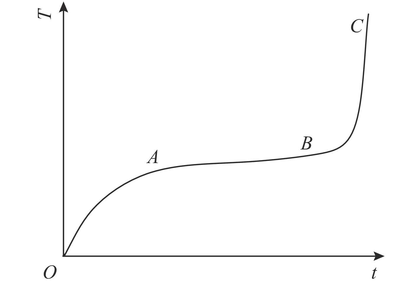
Fig. 1. Bridge wire temperature rise curve
![Non-uniform TML model of the hot bridge-wire EED[23]](/richHtml/qjglzs/2023/35/6/063001/img_2.jpg)
Fig. 2. Non-uniform TML model of the hot bridge-wire EED[23]
Fig. 3. Experimental setup to determine the electrical energy for ignition of EED[25]
Fig. 4. Schematic diagram of the capacitor discharge unit[26]
Fig. 5. Principle of electromagnetic radiation experiment[27]
Fig. 6. Optical path diagram of fiber optic fluorescence pyrometry
Fig. 7. Schematic diagram of white light interference type fiber optic temperature measurement device
Fig. 8. Schematic diagram of GaAs fiber optic temperature measurement device[37]
Fig. 9. System diagram[39]
Fig. 10. Test set up for measurement of induced current[41]
Fig. 11. Infrared fiber optic temperature measurement system[43]
Fig. 12. Radiation test layout diagram[45]
Fig. 13. Continuous wave test system
Fig. 14. Impulse test system
|
Table 1. Characteristics of several types of fiber-optic temperature measurement devices

Set citation alerts for the article
Please enter your email address
© Copyright 2018-2021 | Chinese Laser Press. All Rights Reserved 沪ICP备15018463号-20