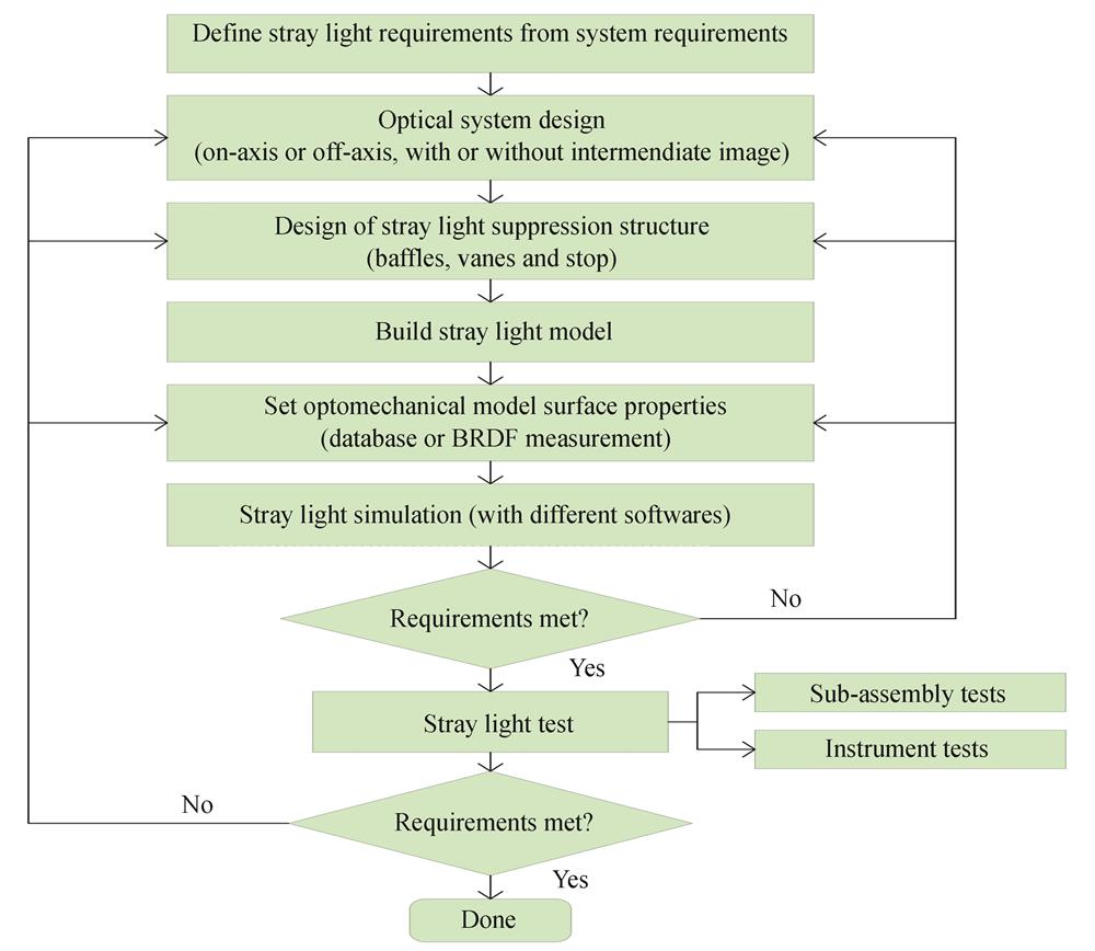
Fig. 1. Stray light engineering process flowchart
Fig. 2. Basic radiative transfer
[13] Fig. 3. Typical stray light phenomenon
[7,9-10] Fig. 4. Classification of stray light suppression methods
Fig. 5. Distribution map of diffraction spikes
[15-16] Fig. 6. Optical system of LISA
[19] Fig. 7. Different shapes of baffle
[6,22-25] Fig. 8. Structure of the vanes in the outer baffle
[26] Fig. 9. Honeycomb light blocking structure
[27-28] Fig. 10. Scattering analysis of honeycomb baffle
[29] Fig. 11. Reflective baffles with vanes
[31-32] Fig. 12. Transmissive two-class three-stage baffle and catadioptric system with inner and outer baffle
[33-34] Fig. 13. Ultra-light baffle
[35-37] Fig. 14. Combined application of total reflection technology and two-stage hood baffle
[38-39] Fig. 15. Expandable sunshields
[40-42] Fig. 16. Deployable sunshield on GF-7 satellite remote sensing camera
[44-46] Fig. 17. Adjustment system with hexapod structure
[47] Fig. 18. Prototype of a deployable telescope based on a ribbon spring
[51] Fig. 19. Deployable membrane sunshield of “MEAYIN Project”
[52-53] Fig. 20. Schematic of sunflower-shaped planet starshade instrument on orbit
[55-57] Fig. 21. Ground test of the sunflower-shaped starshade
[54] Fig. 22. Contrast simulation of the sunflower starshade
[55-57] Fig. 23. Application of Lyot stop in stray light elimination system
[58] Fig. 24. Application of various means of suppression for stray light in SABER telescope
[59] Fig. 25. Large field of view coronagraph optical system
[60-61] Fig. 26. SEM images of different phosphorus compositions in nickel-phosphorus black paint
[62,64] Fig. 27. Automated robot-assisted thermal spray technology
[71] Fig. 28. New super black coating HD-CB99A
[72] Fig. 29. Test spectral curve before and after vacuum-UV,vacuum-electron and vacuum-proton irradia of SCB-1 and PNC
[74-75] Fig. 30. Application of Vantablack paint
[82] Fig. 31. Single-walled carbon nanotube coatings
[83] Fig. 32. Carbon nanotube(CNT)baffle
[84] Fig. 33. Fs laser processing system and morphology of micro/nano structures in circularly polarized laser
[85-86] Fig. 34. Reflection spectra of micro/nano structures at different experimental conditions
[85-86] Fig. 35. James Webb Space Telescope coated with golden thin
[87] Fig. 36. Setup of plasma-enhanced chemical vapor deposition(PECVD)
[90-91] Fig. 37. Reflectivity distribution of graded-index coating
[94] Fig. 38. Influence of the surface topography and particulate contaminants
[9,102-103] Fig. 39. Suppression of surface particle pollutant scattering by single-layer film
[105-106] Fig. 40. CO
2 snow cleaning
[87] Fig. 41. Electrostatic dust removal technology and application
[112,114] Fig. 42. Image method to eliminate ghost image
Fig. 43. An example of image method to eliminate ghost image
[7] Fig. 44. An example of temperature control method
[115] Fig. 45. One-meter vacuum solar telescope NVST
[117] Fig. 46. Comprehensive thermal suppression in VIRCAM
[22] Fig. 47. Gold plating of MAKO spectrometer
[115] Fig. 48. Application of bandpass filtering to suppress stray light in TRACE
[118-119] Fig. 49. Application of bandpass filtering to suppress stray light in SDO-AIA
[120] Fig. 50. Judgment and exclusion of false signal generated by sunlight
[121] Fig. 51. Polarized optical imaging eliminates glare
[123] Fig. 52. Instant dehazing of images using polarization
[123] Fig. 53. Application of circularly polarized light in the restoration of polarized imaging in turbid media
[125] Fig. 54. Polarization-based imaging for clear underwater vision in natural illumination
[126] Fig. 55. Image comparison before and after using the edge method
[127] Fig. 56. Numerical aperture method to suppress stray light
Fig. 57. Application of nonlinear optimization algorithm in image correction
[130] Fig. 58. Application of deconvolution algorithm in image correction of asteroid Vesta
[131] Fig. 59. Application of sub-image adaptive algorithms in multispectral image correction of SJ-9A
[132-134] Fig. 60. Correction of stray light by matrix method
[135] Fig. 61. Geometry for the definition of BRDF,BTDF and BSDF
[26,136-137] Fig. 62. Picture of the scatterometer
[139-140] Fig. 63. Structure of the BRDF Scatterometer
Fig. 64. Facility of the veiling glare index
[1,173] Fig. 65. The measurement which uses box type as exposure source
[11,175-176] Fig. 66. Point source transmittance stray light test facility of the Utah State University
[68] Fig. 67. Point source transmittance stray light test facility of the BATC
[177-178] Fig. 68. Point source transmittance stray light test station developed by XIOPM
[179] Fig. 69. Self-developed of black glass and its application in PST test system
[180-181] Fig. 70. Optical axis alignment device of collimator and optomechanical system in stray light test
[182] Fig. 71. Accuracy analysis of the point source transmittance test system
[183] Fig. 72. Structure and result analysis based on time-resolved PST test system
[184] Fig. 73. Point source transmittance test station in the form of vacuum chamber
[8,185-186] | Name | Manufacturer | Country | Type | Waveband | Notes |
|---|
| Aeroglaze Z306 | Lord Corp. | US | Paint | VIS-LWIR | Diffuse black | | Aeroglaze Z302 | Lord Corp. | US | Paint | VIS* | Specular black. ∗Published data available only for VIS. | | 463-3-8 | AkzoNobel Aerospace Coatings | Netherlands | Paint | VIS-LWIR | Diffuse black. Often used for cold shields. | | 443-3-8 | AkzoNobel Aerospace Coatings | Netherlands | Paint | VIS-LWIR | Specular black | | Nextel Suede | Mankiewicz | Germany | Paint | VIS-LWIR | Diffuse black | | Ball IR Black(BIRB) | Ball Aerospace and Technologies Corp. | US | Etched electroless nickel | VIS-LWIR | Diffuse black | | MH21 | Alion Science and Technology Corp. | US | Paint | VIS-LWIR | Diffuse black | | MH2200 | Alion Science and Technology Corp. | US | Paint | VIS-LWIR | Diffuse black | | Pioneer Optical Black | Pioneer Metal Finishing | US | Anodize | VIS-SWIR | Diffuse black | | Light Absorbing Black-Out Material | Edmund Optics,Inc. | US | Flocking paper | VIS* | Diffuse black. ∗Published data available only for VIS. | | Cerablak | Applied Thin Films,Inc. | US | Fused powder | VIS-LWIR | Diffuse black. Can withstand temperatures up to 1 400 C. | | Epner Laser Black | Epner Technology Inc. | UK | Black oxide | VIS-LWIR | Diffuse black. Very low TIS,and very fragile. | | Ebonol-C | n Science Corp. | US | Anodize | VIS-LWIR | Diffuse black. Very low TIS,and very fragile. | | Deep Space Black | n Science Corp. | US | Anodize | VIS-LWIR | Diffuse black. Very low TIS,and very fragile. | | Tiodize | Tiodize Co.,Inc. | US | Anodize | VIS-LWIR | Diffuse black,titanium substrate only. | | PT-401 | Products,Techniques Inc. | US | Paint | VIS-LWIR | Specular black | | AK-512 | | Russia | Paint | VIS-LWIR | Diffuse black | | Metal Velvet | Acktar | Israel | Paint | VIS-NIR | Diffuse black | | PNC | MAP | France | Paint | VIS-NIR | Diffuse black | | SB-3/SB-3A | Shanghai institute of Organic Chemistry | China | Paint | VIS-LWIR | Diffuse black |
|
Table 1. Widely used black surface treatments
[9] | Name | Solar absorptivity | TML/% | CVCM/% | Application |
|---|
| ERB-2B | 0.94~0.96 | 1.63 | 0.01 | Spacecraft,satellites | | SB-3 | 0.96~0.97 | 2.34 | 0.04 | Spacecraft,satellites | | Es951 | 0.95~0.97 | - | - | Ground thermal,optical system,etc. | | SH96 | 0.94~0.96 | - | - | Ground thermal,optical system,etc. | | SB-3A | 0.97~0.98 | - | - | Optical system |
|
Table 2. Performance of black thermal control coating and its appliances in China
[62] | Company | Scatterometer type | Performance |
|---|
| Surface Optics Corporation | SOC-200 BDR | Wavelength:0.30~10.6 μm Incident angles:0°~80° Scattering angles:-85°~+85° Azimuth angles:0°~360° | | Light Tec | REFLET 180S | Wavelength:0.40~1.80 μm Incident angles:0°~180° Scattering angles:-90°~+90° Azimuth angles:-90°~+90° Angular resolution:0.01° | | The Scatter Works Inc | TSW CASI | Wavelength:0.325~10.6 μm Incident angles:0°~85° Scattering angles:0°~360° Angular resolution:0.001° Linear resolution:0.01 mm | | TMA Technologies. Inc | TMA TASC | Wavelength:0.633 μm,0.850 μm,1.55 μm,3.39 μm,10.6 μm Incident angles:0°~135° Azimuth angles:0°~360° Test accuracy:1% Dynamic range:1012 | | Fraunhofer Institute | ALBATROSS | Wavelength:0.325~10.6 μm Incident angles:0°~85° Scattering angles:-90°~90°(ISO5) |
|
Table 3. The main commercial BRDF measurement devices
[139,143] | Software type | Company | Compatibility | Modeling ability | Analysis | Usage |
|---|
| FRED | Photon Engineering | CODE V、Zemax、OSLO | Poor | Moderate | More in abroad | | ASAP | Breault Research Organization | CODE V、Zemax、SAYNOPSYSTM、SOLIDWORKS | Poor | Best | More in abroad | | LightTools | Optical Research Associates | CODE V、Zemax | Better | Better | Less | | TracePro | Lambda Research Corporation | CODE V、Zemax、OSLO、SOLIDWORKS | Better | Better | More in domestic |
|
Table 4. Comparison of various stray light analysis softwares
[169] 
![Basic radiative transfer[13]](/richHtml/gzxb/2022/51/7/0751406/img_02.jpg)
