[1] S. Takahashi, L. C. Brunel, D. T. Edwards, J. V. Tol, G. Ramian, S. Han, M. S. Sherwin. Nature, 489, 409(2012).
[2] L. Young, E. P. Kanter, B. Krässig, Y. Li, A. M. March, S. T. Pratt, R. Santra, S. H. Southworth, N. Rohringer, L. F. Dimauro, G. Doumy, C. A. Roedig, N. Berrah, L. Fang, M. Hoener, P. H. Bucksbaum, J. P. Cryan, S. Ghimire, J. M. Glownia, D. A. Reis, J. D. Bozek, C. Bostedt, M. Messerschmidt. Nature, 466, 56(2010).
[3] T. R. Barends, L. Foucar, S. Botha, R. B. Doak, R. L. Shoeman, K. Nass, J. E. Koglin, G. J. Williams, S. Boutet, M. Messerschmidt, I. Schlichting. Nature, 505, 244(2014).
[4] D. H. Bilderback, P. Elleaume, E. Weckert. J. Phys. B At. Mol. Opt. Phys., 38, S773(2005).
[5] K. Tono. High Power Laser Sci. Eng., 5, e7(2017).
[6] W. Ackermann, G. Asova, V. Ayvazyan, A. Azima, N. Baboi, J. Bahr, V. Balandin, B. Beutner, A. Brandt, A. Bolzmann, R. Brinkmann, O. I. Brovko, M. Castellano, P. Castro, L. Catani, E. Chiadroni, S. Choroba, A. Cianchi, J. T. Costello, D. Cubaynes, J. Dardis, W. Decking, H. Delsim-Hashemi, A. Delserieys, G. D. Pirro, M. Dohlus, S. Dusterer, A. Eckhardt, H. T. Edwards, B. Faatz, J. Feldhaus, K. Flottmann, J. Frisch, L. Fröhlich, T. Garvey, U. Gensch, C. Gerth, M. Gorler, N. Golubeva, H. J. Grabosch, M. Grecki, O. Grimm, K. Hacker, U. Hahn, J. H. Han, K. Honkavaara, T. Hott, M. Hüning, Y. Ivanisenko, E. Jaeschke, W. Jalmuzna, T. Jezynski, R. Kammering, V. Katalev, K. Kavanagh, E. T. Kennedy, S. Khodyachykh, K. Klose, V. Kocharyan, M. Korfer, M. Kollewe, W. Koprek, S. Korepanov, D. Kostin, M. Krassilnikov, G. Kube, M. Kuhlmann, C. L. S. Lewis, L. Lilje, T. Limberg, D. Lipka, F. Löhl, H. Luna, M. Luong, M. Martins, M. Meyer, P. Michelato, V. Miltchev, W. D. Moller, L. Monaco, W. F. O. Muller, A. Napieralski, O. Napoly, P. Nicolosi, D. Nolle, T. Nunez, A. Oppelt, C. Pagani, R. Paparella, N. Pchalek, J. Pedregosa-Gutierrez, B. Petersen, B. Petrosyan, G. Petrosyan, L. Petrosyan, J. Pfluger, E. Plonjes, L. Poletto, K. Pozniak, E. Prat, D. Proch, P. Pucyk, P. Radcliffe, H. Redlin, K. Rehlich, M. Richter, M. Roehrs, J. Roensch, R. Romaniuk, M. Ross, J. Rossbach, V. Rybnikov, M. Sachwitz, E. L. Saldin, W. Sandner, H. Schlarb, B. Schmidt, M. Schmitz, P. Schmuser, J. R. Schneider, E. A. Schneidmiller, S. Schnepp, S. Schreiber, M. Seidel, D. Sertore, A. V. Shabunov, C. Simon, S. Simrock, E. Sombrowski, A. A. Sorokin, P. Spanknebel, R. Spesyvtsev, L. Staykov, B. Steffen, F. Stephan, F. Stulle, H. Thom, K. Tiedtke, M. Tischer, S. Toleikis, R. Treusch, D. Trines, I. Tsakov, E. Vogel, T. Weiland, H. Weise, M. Wellhofer, M. Wendt, I. Will, A. Winter, K. Wittenburg, W. Wurth, P. Yeates, M. V. Yurkov, I. Zagorodnov, K. Zapfe. Nat. Photonics, 1, 336(2007).
[7] P. Emma, R. Akre, J. Arthur, R. Bionta, C. Bostedt, J. Bozek, A. Brachmann, P. Bucksbaum, R. Coffee, F.- J. Decker, Y. Ding, D. Dowell, S. Edstrom, A. Fisher, J. Frisch, S. Gilevich, J. Hastings, G. Hays, Ph. Hering, Z. Huang, R. Iverson, H. Loos, M. Messerschmidt, A. Miahnahri, S. Moeller, H.-D. Nuhn, G. Pile, D. Ratner, J. Rzepiela, D. Schultz, T. Smith, P. Stefan, H. Tompkins, J. Turner, J. Welch, W. White, J. Wu, G. Yocky, J. Galayda. Nat. Photonics, 4, 641(2010).
[8] E. Allaria, R. Appio, L. Badano, W. A. Barletta, S. Bassanese, S. G. Biedron, A. Borga, E. Busetto, D. Castronovo, P. Cinquegrana, S. Cleva, D. Cocco, M. Cornacchia, P. Craievich, I. Cudin, G. D’Auria, M. D. Forno, M. B. Danailov, R. D. Monte, G. De Ninno, P. Delgiusto, A. Demidovich, S. D. Mitri, B. Diviacco, A. Fabris, R. Fabris, W. Fawley, M. Ferianis, E. Ferrari, S. Ferry, L. Froehlich, P. Furlan, G. Gaio, F. Gelmetti, L. Giannessi, M. Giannini, R. Gobessi, R. Ivanov, E. Karantzoulis, M. Lonza, A. Lutman, B. Mahieu, M. Milloch, S. V. Milton, M. Musardo, I. Nikolov, S. Noe, F. Parmigiani, G. Penco, M. Petronio, L. Pivetta, M. Predonzani, F. Rossi, L. Rumiz, A. Salom, C. Scafuri, C. Serpico, P. Sigalotti, S. Spampinati, C. Spezzani, M. Svandrlik, C. Svetina, S. Tazzari, M. Trovo, R. Umer, A. Vascotto, M. Veronese, R. Visintini, M. Zaccaria, D. Zangrando, M. Zangrando. Nat. Photonics, 6, 699(2012).
[9] T. Ishikawa, H. Aoyagi, T. Asaka, Y. Asano, N. Azumi, T. Bizen, H. Ego, K. Fukami, T. Fukui, Y. Furukawa, S. Goto, H. Hanaki, T. Hara, T. Hasegawa, T. Hatsui, A. Higashiya, T. Hirono, N. Hosoda, M. Ishii, T. Inagaki, Y. Inubushi, T. Itoga, Y. Joti, M. Kago, T. Kameshima, H. Kimura, Y. Kirihara, A. Kiyomichi, T. Kobayashi, C. Kondo, T. Kudo, H. Maesaka, X. M. Mar’echal, T. Masuda, S. Matsubara, T. Matsumoto, T. Matsushita, S. Matsui, M. Nagasono, N. Nariyama, H. Ohashi, T. Ohata, T. Ohshima, S. Ono, Y. Otake, C. Saji, T. Sakurai, T. Sato, K. Sawada, T. Seike, K. Shirasawa, T. Sugimoto, S. Suzuki, S. Takahashi, H. Takebe, K. Takeshita, K. Tamasaku, H. Tanaka, R. Tanaka, T. Tanaka, T. Togashi, K. Togawa, A. Tokuhisa, H. Tomizawa, K. Tono, S. Wu, M. Yabashi, M. Yamaga, A. Yamashita, K. Yanagida, C. Zhang, T. Shintake, H. Kitamura, N. Kumagai. Nat. Photonics, 6, 540(2012).
[10] T. Tajima, J. M. Dawson. Phys. Rev. Lett., 43, 267(1979).
[11] S. P. Mangles, C. D. Murphy, Z. Najmudin, A. G. Thomas, J. L. Collier, A. E. Dangor, E. J. Divall, P. S. Foster, J. G. Gallacher, C. J. Hooker, D. A. Jaroszynski, A. J. Langley, W. B. Mori, P. A. Norreys, F. S. Tsung, R. Viskup, B. R. Walton, K. Krushelnick. Nature, 431, 535(2004).
[12] C. G. R. Geddes, C. Toth, J. V. Tilborg, E. Esarey, C. B. Schroeder, D. Bruhwiler, C. Nieter, J. Cary, W. P. Leemans. Nature, 431, 538(2004).
[13] J. Faure, Y. Glinec, A. Pukhov, S. Kiselev, S. Gordienko, E. Lefebvre, J. P. Rousseau, F. Burgy, V. Malka. Nature, 431, 541(2004).
[14] J. S. Liu, C. Q. Xia, W. T. Wang, H. Y. Lu, C. Wang, A. H. Deng, W. T. Li, H. Zhang, X. Y. Liang, Y. X. Leng, X. M. Lu, C. Wang, J. Z. Wang, K. Nakajima, R. X. Li, Z. Z. Xu. Phys. Rev. Lett., 107(2011).
[15] A. J. Gonsalves, K. Nakamura, C. Lin, D. Panasenko, S. Shiraishi, T. Sokollik, C. Benedetti, C. B. Schroeder, C. G. R. Geddes, J. V. Tilborg, J. Osterhoff, E. Esarey, C. Toth, W. P. Leeman. Nat. Phys., 7, 862(2012).
[16] W. P. Leemans, A. J. Gonsalves, H. S. Mao, K. Nakamura, C. Benedetti, C. B. Schroeder, C. Tóth, J. Daniels, D. E. Mittelberger, S. S. Bulanov, J. L. Vay, C. G. R. Geddes, E. Esarey. Phys. Rev. Lett., 113(2014).
[17] W. T. Wang, W. T. Li, J. S. Liu, Z. J. Zhang, R. Qi, C. H. Yu, J. Q. Liu, M. Fang, Z. Y. Qin, C. Wang, Y. Xu, F. X. Wu, Y. X. Leng, R. X. Li, Z. Z. Xu. Phys. Rev. Lett., 117(2016).
[18] N. A. M. Hafz, S. Li, G. Li, M. Mohammad, M. Zeng, J. Zhang. High Power Laser Sci. Eng., 4, e24(2016).
[19] C. Rechatin, J. Faure, A. Benismail, J. Lim, R. Fitour, A. Specka, H. Videau, A. Tafzi, F. Burgy, V. Malka. Phys. Rev. Lett., 102(2009).
[20] M. Mirzaie, S. Li, M. Zeng, N. A. Hafz, M. Chen, G. Y. Li, Q. J. Zhu, H. Liao, T. Sokollik, F. Liu, Y. Y. Ma, L. M. Chen, Z. M. Sheng, J. Zhang. Sci. Rep., 5, 14659(2015).
[21] Z. Huang, K.- J. Kim. Phys. Rev. Accel. Beams, 10(2007).
[22] Z. J. Zhang, J. S. Liu, W. T. Wang, W. T. Li, C. H. Yu, Y. Tian, R. Qi, C. Wang, Z. Y. Qin, M. Fang, J. Q. Liu, K. Nakajima, R. X. Li, Z. Z. Xu. New J. Phys., 17(2015).
[23] T. I. Smith, J. M. J. Madey, L. R. Elias, D. A. G. Deacon. J. Appl. Phys., 50, 4580(1979).
[24] Z. Huang, Y. Ding, C. B. Schroeder. Phys. Rev. Lett., 109(2012).
[25] P. Baxevanis, Y. Ding, Z. Huang, R. Ruth. Phys. Rev. Accel. Beams, 17(2014).
[26] Q. Jia, H. Li. Phys. Rev. Accel. Beams, 20(2017).
[27] R. Bonifacio, C. Pellegrini, L. M. Narducci. Opt. Commun., 50, 373(1984).
[28] Z. Qin, C. Yu, W. Wang, J. Liu, W. Li, R. Qi, Z. Zhang, J. Liu, M. Fang, K. Feng, Y. Wu, L. Ke, Y. Chen, Y. Xu, Y. Leng, C. Wang, R. Li, Z. Xu. Phys. Plasmas, 25(2018).
[29] M. Fang, W. Wang, Z. Zhang, J. Liu, C. Yu, R. Qi, Z. Qin, J. Liu, K. Feng, Y. Wu, C. Wang, T. Liu, D. Wang, Y. Xu, F. Wu, Y. Leng, R. Li, Z. Xu. Chin. Opt. Lett., 16(2018).
[30] T. Liu, T. Zhang, D. Wang, Z. Huang. Phys. Rev. Accel. Beams, 20(2017).
[31] S. Reiche. Nucl. Instrum. Methods Phys. Res A, 429, 243(1999).
[32] I. A. Vartanyants, A. Singer. New J. Phys., 12(2010).
[33] P. Baxevanis, Z. Huang, R. Ruth, C. B. Schroeder. Phys. Rev. Accel. Beams, 18(2015).
 beam) with a large energy spread (
 ) to enhance the free-electron laser (FEL) gain. For a dispersed
 beam in a PU, the resonant condition is satisfied for the center electrons, while the frequency detuning increases for the off-center electrons, inhibiting the growth of the radiation. The PU can act as a filter for selecting the electrons near the beam center to achieve the radiation. Although only the center electrons contribute, the radiation can be enhanced significantly owing to the high-peak current of the beam. Theoretical analysis and simulation results indicate that this method can be used for the improvement of the radiation performance, which has great significance for short-wavelength FEL applications.
 GeV), high-peak current (
 kA), and low-emittance (
 ) electron beams (
 beams) using laser wakefield accelerators (LWFAs)
[
beams) using laser wakefield accelerators (LWFAs)
[
 beams usually have a large energy spread of a few percent
[
beams usually have a large energy spread of a few percent
[
 beam
[
beam
[
 beam must be matched with the transverse gradient field of the TGU to satisfy the resonant condition
[
beam must be matched with the transverse gradient field of the TGU to satisfy the resonant condition
[
 beam is introduced.
 beam from the LWFA. Our scheme has no need of extra field for correcting the orbit deflection induced by the field gradient and is easy to implement. In the proposed scheme, the energy of the
 beam is dispersed with its horizontal position so that only the center electrons satisfy the resonant condition, but the frequency detuning increases when the electrons deviate from the beam center, which inhibits the radiation growth. This mechanism can be regarded as a selection process, in which the PU acts as a filter for selecting the electrons near the beam center to achieve the radiation. Although only the center electrons contribute, the radiation can be enhanced owing to the high-peak current of the
 beam. Theoretical analysis and numerical simulations demonstrate the feasibility of a self-amplified spontaneous emission (SASE) FEL with sub-gigawatt power, a narrow bandwidth (
 ) and good transverse coherence in the proposed scheme with typical parameters of the
 beam from the LWFA.
 beam with normalized energy
 propagating through an undulator with the period
 and strength parameter
 , the on-axis radiation wavelength is
 . To obtain a high-gain FEL, the beam energy spread
 should satisfy
[
should satisfy
[

 is the dimensionless Pierce parameter, which can be defined as
[
is the dimensionless Pierce parameter, which can be defined as
[

 is the peak current,
 is the Alfvén current,
 is the root-mean-square (RMS) transverse beam size,
 , and
, and
 , with
 . However, satisfying Equation (
 beams from LWFAs.
 beam with horizontal dispersion
 , the horizontal position of the electrons depends on the energy:
 , as shown in Figure
 beams without and with the dispersion are shown in Figures
 beam increases to
 , and the density of the
 beam decreases. Using the method of perturbation analysis and integration along the unperturbed trajectories
[
beam decreases. Using the method of perturbation analysis and integration along the unperturbed trajectories
[


 depends on the properties of the
 beam and not the type of undulator. A significantly reduced effective energy spread is required for optimum operation of the FEL; thus, we can usually approximate
 .
. beam at the entrance of the undulator are shown in Table
 without external focusing, it is reasonable to assume a beta function of
 . Thus, the initial transverse beam size is estimated as
 . The horizontal dispersion is chosen as
 cm, which is the optimum dispersion of the beam according to the simulation results presented in the next section. Here, only the linear dispersion is considered in our simulation. It is noted that the beta function is the one before introducing the dispersion
[
cm, which is the optimum dispersion of the beam according to the simulation results presented in the next section. Here, only the linear dispersion is considered in our simulation. It is noted that the beta function is the one before introducing the dispersion
[
 .
.


 beam and undulator parameters used in our study for EUV and soft X-ray FELs.
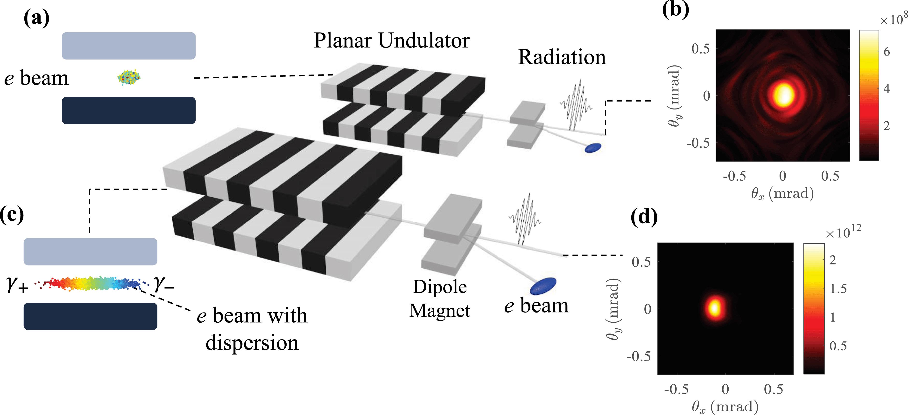
 beams with (blue) and without (black) the horizontal dispersion. For a 6 m undulator, the radiation power increases by almost three orders of magnitude when the horizontal dispersion of the
 beam is introduced. Figure
 beam. Figures
 -beam dispersion, the divergence angle is large owing to the large emittance of the
 beam and the relatively low gain, as shown in Figure
 beam, as shown in Figure
 beam and the undulator considered in Ref. [
 cm. Reasonably assuming a beta function of
 m, we obtain an initial beam size of
 . After dispersion, the horizontal beam size increases to
 . The radiation power is improved by two orders of magnitude and reaches saturation with a properly dispersed
 beam, as shown in Figure
 beam owing to the short duration of the beam, as shown in Figure
 beam in the PU scheme. Taking the 30 nm radiation as an example, we now study the properties of the radiation with different dispersions of the
 beam. Figure
 is satisfied in all of our simulation cases for the TGU scheme. The radiation power is significantly enhanced by introducing the
 -beam dispersion. As discussed previously, Equation (
 beam is introduced, the localized energy spread decreases, as does the effective FEL parameter. However, compared with the effective FEL parameter, the localized energy spread decreases rapidly as the dispersion increases, as indicated by Equations (
 beam, the higher-order modes can be suppressed. Thus, the SASE FEL can reach almost full transverse coherence before saturation, and the radiation emittance is almost given by the diffraction-limited radiation emittance
 , where
 is the resonant wavelength of the radiation. However, the large transverse beam size due to the dispersion provides enough transverse space for the high-order modes to couple with the
 beam, reducing the transverse coherence. The transverse mode parameter can be defined as
[
beam, reducing the transverse coherence. The transverse mode parameter can be defined as
[

 is the radiation emittance,
 and
and
 are the RMS radius and the far-field divergence half-angle of the radiation, respectively
[
are the RMS radius and the far-field divergence half-angle of the radiation, respectively
[
 , where
 is the RMS waist radius
[
is the RMS waist radius
[
 beam for both the PU and TGU schemes. Without the dispersion,
 , indicating that the transverse coherence is poor. After the dispersion of the
 beam is introduced, the coherent properties are improved in both schemes. For obtaining the best transverse coherence of the radiation, the optimum dispersion is 1.5 and 2.5 cm for the TGU and PU scheme, respectively. Figure
 cm. That is, for the high-order modes, it is more difficult to couple with the
 beam in the PU scheme than in the TGU scheme when the horizontal dispersion is large, which may provide additional evidence that the radiation emitted by the center electrons dominates.
 beam having a horizontal dispersion, whose phase-space distribution is schematically illustrated in Figure
 beam and compare between the PU and TGU schemes. A 3D theoretical model based on the analysis of the eigenmode was established in Ref. [
 and the complex growth rate
 , has a solution of the form
 . The growth rate with a negative imaginary part represents the growth mode. An analytical solution is obtained for the case where the transverse emittance and focusing are negligible (which is suitable for
 beams from an LWFA owing to the small emittance), and the scaled growth rate
 of a growing mode is obtained using the relation
[
of a growing mode is obtained using the relation
[

 and
and
 are the diffraction parameters,
 ,
,
 ,
,
 and
and
 are the transverse mode numbers, and
 , where
 and
and
 are the scaled growth rate and the detuning parameter, respectively. Here,
 is the dimensionless detuning variable which represents the normalized deviation of the radiation wavelength
 from the resonant wavelength
 according to Refs. [
 is the scaled TGU resonant parameter, where
 when the resonant condition is satisfied. The effective operation of an FEL setup requires a significantly reduced effective energy spread; thus, we can make the large-dispersion approximate
 .
. . We make the simple assumption that
 , which means that all the electrons satisfy the resonant condition under the large-dispersion approximation in both the PU and TGU schemes. However, the radiation wavelength shifts in the PU scheme when the energy of the electron deviates from
 , which can be described by the frequency-detuning parameter
 . The difference between the TGU and PU schemes is that the frequency detuning is independent upon the transverse position in the TGU when the matching condition is fulfilled (here, we set
 under the large-dispersion approximation). In the PU scheme, the detuning increases when the electron deviates from the horizontal beam center. We define a detuning parameter in the PU scheme that depends on the horizontal position
 :
:

 -beam horizontal dispersion of 2.5 cm. For this dispersion value, the corresponding parameters are given as
 ,
,
 , and
, and
 . The growth rate remains constant at any horizontal position in the TGU scheme and decreases when the electron deviates from the beam center in the PU scheme. Once the horizontal position of the electron exceeds the blue covered region shown in Figure
 beams from the LWFA.
 beam is
 cm. Figure
 . However, when the halfwidth of the slit exceeds
 , the radiation power changes little with the increase of the slit width in the PU scheme. For the cases with the collimator (the halfwidth of the slit is
 ) and without the collimator, the average radiation power is 84 and 90 MW, respectively, in the PU scheme. That is, approximately 37% of the electrons near the beam center contribute more than 90% of the total radiation power. Figures
 beam from the LWFA. Although only part of the electrons near the beam center contribute to the radiation, intense FEL radiation can be obtained owing to the high-peak current of the
 beam. The radiation pulses can be sub-gigawatt level in power with a narrow bandwidth below 1% and good transverse coherence without seeding. The proposed scheme is easy to implement, which is significant for the experimental realization of the LWFA-based FEL. Further investigations on driving short-wavelength LWFA-based FELs are ongoing.