Colliding of two counter-propagating laser pulses is a widely used approach to create a laser field or intensity surge. We experimentally demonstrate broadband coherent terahertz (THz) radiation generation through the interaction of colliding laser pulses with gas plasma. The THz radiation has a dipole-like emission pattern perpendicular to the laser propagation direction with a detected peak electric field 1 order of magnitude higher than that by single pulse excitation. As a proof-of-concept demonstration, it provides a deep insight into the physical picture of laser–plasma interaction, exploits an important option to the promising plasma-based THz source, and may find more applications in THz nonlinear near-field imaging and spectroscopy.
1. INTRODUCTION
As a mixture of charged particles, plasma can be modulated into a periodic structure by external electromagnetic fields. Owing to the periodic distribution of charge density, modulated plasma can be utilized as optical elements like plasma gratings [1] or plasma photonic crystals [2]. The periodic structure of plasma can oscillate or propagate in a certain direction, forming a plasma wave, which can be developed as a radiation emitter [3] or frequency converter [4,5]. Colliding laser pulses, also known as counter-propagating laser beams, have been investigated for decades and applied to ultrafast oscillators to create femtosecond laser pulses [i.e., colliding-pulse mode-locking (CPM)] [6–8]. As an efficient tool to generate a laser field or intensity surge at the colliding point, colliding laser pulses can be used to stimulate the periodic structure of plasma through laser–plasma interaction. Potential applications based on the colliding pulses in plasma were proposed, such as the laser amplifier [9–11], high-harmonic generation [12], and electron accelerator [13,14]. More recently, the colliding laser pulses in plasma have been proposed as a promising plasma-based terahertz (THz) source, theoretically [15–17].
Benefiting from the absence of phonon absorption, the air plasma-based THz source can emit intense THz waves with ultrabroad bandwidth [18], which is crucial for exploiting many practical THz applications [19]. Different approaches, such as asymmetrical field excitation [20–22] and high voltage DC-bias [23,24], were proposed to enhance the optical-to-THz conversion efficiency. Besides, research works were carried out in order to convert plasma oscillations to electromagnetic waves directly [25–27]. Other than the THz emission from air–plasma filament, THz emission from a micro-plasma was investigated experimentally [28] and theoretically [29]. Owing to its micrometer-scale plasma length and lateral emission pattern, its potential applications in THz microscopy were discussed [28,30]. A novel concept based on the use of colliding pulses to stimulate and convert plasma oscillations to THz waves was proposed recently, indicating that narrow linewidth electromagnetic radiation can be emitted through the interaction of two identical counter-propagating laser pulses in plasma [15,31,32]. More recently, theoretical simulations predicted that broadband THz radiation can be emitted by the interaction of two colliding laser pulses with a small frequency difference in a preformed underdense plasma [16,17]. A laser chirping technique can be used to modify and enhance the optical-to-THz conversion efficiency from two-color laser-induced plasma by tuning the time delay between the chirped fundamental and second-harmonic pulses [33]. Such a method can also be used to achieve the frequency detuning between two chirped laser pulses in the counter-propagating geometry [34].
2. THEORETICAL BASIS
When two laser pulses counter-propagate along the laser axis, the laser electric field takes this form:where are the spatial-temporal profiles of the laser pulses. are the frequencies of the two pulses, and their frequency difference is defined as . are the wavenumbers of the laser pulses. The ponderomotive potential can be calculated using time-averaged hydrodynamic and Maxwell’s equations, where the first and the second terms in the equation represent the ponderomotive potentials induced by individual laser pulses, respectively, while the third term describes the ponderomotive potential contributed by the interaction of the colliding pulses. The third term dominates the equation due to its large gradient along the laser propagation axis , indicating a much larger ponderomotive force compared to the first and the second terms. As Eq. (2) describes, the ponderomotive force forms a spatially localized, moving train of periodic potential wells propagating along the axis , in which the electrons are trapped. Driven by the propagating potential wells, the trapped electrons move along the laser axis at a phase velocity . Therefore, the movement of the trapped electrons can form a transient current and consequently build up a dipole electric field through the charge separation between the trapped electrons and the quasi-stationary ions in plasma. The generation of the THz wave from colliding pulses is a two-step process. In the first step, the transient current formed by the directional movement of trapped electrons emits a few-cycle THz pulse when two colliding laser pulses interact with each other in the gas plasma. The second step starts after the passage of the colliding laser pulses, corresponding to the equilibrium restoration process. Driven by the restoring force of the dipole electric field, the electrons released from the ponderomotive potential wells oscillate along the laser axis at the plasma frequency and finally restore to their equilibrium, emitting a multi-cycle THz wave with a narrow frequency band centered at the plasma frequency. It is noteworthy that electrons moving along the laser axis are essentially an electron wave in the plasma, whose frequency is determined by the frequency detuning of two colliding laser pulses. Similar to the electromagnetic wave propagating in the plasma, an electron wave with a frequency much lower than the plasma frequency is heavily damped by the plasma. As a result, the frequency difference between two colliding pulses should at least be comparable with the plasma frequency to mitigate the damping effect in the plasma and consequently improve the THz generation efficiency. Moreover, the THz radiation is emitted perpendicularly to the laser axis under tight focusing conditions [16,17]. In contrast to THz emission from dipole-like charges traveling behind the laser ionization front in single pulse excited laser filament, the THz emission induced by colliding pulses is spatially localized since the THz radiation can only be emitted from the interaction zone of colliding pulses. The longitudinal and transverse dimensions of the THz emitter are determined by the pulse width and the focal spot size of the laser pulses, respectively. Therefore, the size of the THz emitter can be on the micrometer scale by using tightly focused ultrashort laser pulses. Such a THz emitter has the potential to obtain micrometer-scale resolution in near-field microscopes.
Sign up for Photonics Research TOC. Get the latest issue of Photonics Research delivered right to you!Sign up now
3. EXPERIMENTAL SETUP
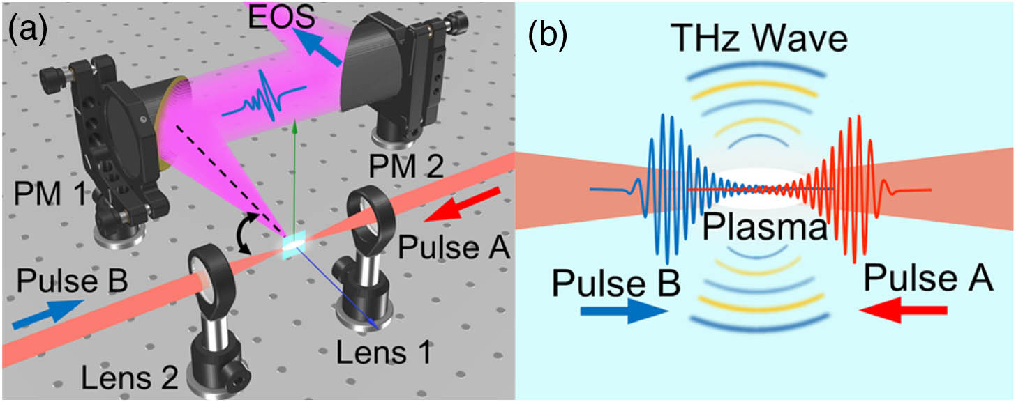
In this paper, we experimentally demonstrate the broadband THz wave generation by ionizing the air molecules using colliding laser pulses. The experimental setup is shown in Fig. 1(a). Laser pulses are delivered by a femtosecond Ti:sapphire amplified system with an 800 nm central wavelength at a 1 kHz repetition rate, a pulse width of , and a bandwidth of . The laser pulse is split by a 50:50 broadband beam splitter into pulses A and B with identical spectrum and pulse energy. To maximize the THz wave generation, negatively chirped pulses are achieved by changing group delay dispersion (GDD) induced by the pulse compressor inside the amplified laser system. Pulses A and B, focused from opposite directions by two 2 in. effective focal length (EFL) lenses, collide with each other and, thus, form a plasma for THz wave generation. The lenses can move along the laser propagation axis to optimize the spatial overlap of the two focal points. The optical path length of pulse B can be varied to tune the relative time delay between pulses A and B, while the optical path in the arm of pulse A is fixed. The generated THz radiation is collected and collimated by a parabolic mirror (PM1) in the direction perpendicular to the laser axis and then refocused by a second parabolic mirror (PM2) onto a 1-mm-thick cut Zn–Te crystal for electro-optic sampling (EOS). The standard THz EOS detection system used in the experiment can be rotated around the plasma horizontally to measure the angular distribution of the THz radiation.
Figure 1.(a) Experimental setup: PM1 and PM2, parabolic mirrors; EOS, electro-optic sampling. (b) Schematic diagram of the THz generation process from colliding laser pulses.
Figure 1(b) shows the schematic diagram of the THz generation process from colliding pulse-induced plasma. The leading edges of pulses A and B ionize the air and form a plasma near the optical focal point, providing a plasma zone for the subsequent THz radiation generation process. Taking into account the tight focusing condition (8 mm beam diameter and 2 in. EFL, i.e., ), the 800 μJ pulse energy of each pulse, and the pulse width of used in our experiment, the laser intensity at the focal point is estimated to be . Under such a condition, the electron density inside the plasma is estimated to be on a scale of [35–37]. Therefore, the plasma frequency falls in the THz range (, where is the electron charge, is the electron mass, and is the electron density). The frequency difference between pulses A and B () is achieved by imparting additional GDD to the pulses, which separates different frequency components and stretches the pulses in the time domain. As a result, the frequency of the chirped pulses is a function of time (i.e., , , where , , and represent the central wavelength, the chirp rate of the laser pulse, and the time delay between pulses A and B, respectively). As the two pulses collide with each other, the frequency difference between the chirped pulses is a function of the time delay at a fixed position [i.e., ]. In this case, the detuning of the pulse frequencies can be realized by finely adjusting the relative delay between the two pulses, allowing different frequency components of the two pulses to interact with each other at a certain spatial position. At the optimized pulse width () and time delay for THz generation in our experiment, the maximum frequency difference between two colliding pulses is approximately estimated to be about 3.9 THz.
4. RESULTS AND DISCUSSION
Through the interaction of the colliding pulses and plasma, broadband THz radiation is emitted laterally, as Fig. 1(b) shows. A typical THz waveform is shown with the black solid line in Fig. 2(a). As a comparison, the red and blue solid curves represent the THz signals generated by individual pulses A and B, respectively. The strength of the THz electric field by colliding pulses is at least 1 order of magnitude higher than that by each individual pulse, and the peak THz electric field is estimated to be . The signal-to-noise ratio of the THz signal generated by colliding pulses is about 200, obtained by means of EOS. The inset of Fig. 2(a) shows the corresponding spectra. The spectrum of the colliding signal is broadband with a bandwidth exceeding 1.5 THz, while its central frequency is obviously higher than that of each individual laser pulse, exhibiting a blueshift shown in the inset of Fig. 2(a). Such a blueshift is mainly attributed to the difference between THz generation processes excited by the colliding pulses and single laser pulse. THz electric field generated by a single laser pulse is dependent on the gradient of the slow-varying intensity profile of the laser pulse, leading to the relatively low central frequency of the THz spectra when the laser pulse with a 220 fs pulse width is used. On the other hand, the THz wave emitted from colliding pulses is mainly dependent on the fast-varying phase term originated from the frequency detuning of the two colliding pulses, leading to a relatively higher central frequency, as shown in the inset of Fig. 2(a). It is noteworthy that no quasi-narrowband peak is observed in the spectrum, which represents the dipole oscillation at the plasma frequency () after the trapped electrons are released from the ponderomotive potential wells. This may be due to the bandwidth limit of the detection system using 1-mm-thick Zn–Te crystal () [38]. It can be seen from Fig. 2(a) that the peak timings of the three signals are different, which can be explained from two aspects. First, as one of the counter-propagating beams is blocked, the focal point of the other beam will move along the laser axis because the nonlinear propagation process of laser pulses is changed as both the laser intensity and plasma density in the plasma region decrease when one of the counter-propagating beams is blocked. Second, pulses A and B do not completely coincide with each other in the time domain after optimizing the THz strength by finely adjusting their relative delay.
Figure 2.(a) Typical waveforms of the THz radiation and the corresponding Fourier transform spectra (inset). Each THz spectrum shown in the inset is normalized to its maximal value for comparison. Black, red, and blue solid lines represent the THz signals by colliding pulses (pulse A and pulse B), pulse A, and pulse B, respectively. (b) Pseudo-color image of THz electric field versus the time delay for THz waveform scan and the relative delay between pulse A and pulse B. (c) Peak THz amplitude as a function of laser pulse width with pulse energies set at 800 μJ and 200 μJ. Negative chirp is applied to stretch the laser pulses shown in the right half, and vice versa. (d) The dependences of peak THz amplitude on laser pulse energy measured at the optimal negative chirp, optimal positive chirp, and zero chirp, respectively.
In order to give a clear overview of the impact of the relative delay between the two pulses on the THz electric field, we apply a two-dimensional scan of the THz electric field versus the time delay and the relative delay, as shown in Fig. 2(b). The relative delay is arbitrarily defined as equal to zero when the THz signal reaches its maximum. From the pseudo-color image, we can see that the THz signal generated by pulse A is not affected by pulse B when pulse A leads pulse B sufficiently, as indicated by the red dashed box. When pulse B keeps approaching pulse A by reducing the relative delay, it starts to collide with pulse A, generating THz radiation through the interaction between the two laser pulses and plasma, as indicated by the black dashed line. For different relative delays, pulse A and pulse B collide at different locations along the laser axis, resulting in different THz electric field strengths. When pulse B leads pulse A sufficiently, the THz signal generated by pulse B can be distinguished from the colliding signal, as indicated by the blue dashed box in Fig. 2(b). When the laser pulse width is , the spatial length of the interaction region between pulses A and B is estimated to be μ. Therefore, the length of the THz emitter along the laser axis is about 60 μm, far less than the wavelength of the THz radiation.
Electrons driven by the pondermotive force move along the laser axis at the phase velocity and form a dipole through charge separation. The dipole-induced electric field increases with the displacement of the moving electrons. The displacement of the electrons increases with time until it reaches the maximum at the time when the ponderomotive force equals the restoring force of the dipole field. As a result, the THz amplitude is proportional to the duration of the electron movement. The increase in laser intensity can strengthen the ponderomotive force, leading to a longer moving duration of the electrons and consequently stronger THz radiation. However, the moving duration of the electrons will not be longer than the interaction duration of the colliding pulses (i.e., pulse width). To clarify the impact of the pulse width on THz generation, we measure the peak THz amplitude as a function of laser pulse width with pulse energies set at 800 μJ and 200 μJ, respectively, as shown in Fig. 2(c). The laser chirp is presented in terms of the GDD imparted to the laser pulses as shown in the top label of Fig. 2(c). The laser pulse width increases with the absolute value of laser chirp, which is marked in the bottom label of Fig. 2(c). The right side of Fig. 2(c) shows the case of negatively chirped pulses, while the case of positively chirped pulses is shown on the left side. For laser pulses stretched by positive or negative chirp, the peak THz amplitude first increases and then decreases with the pulse width for both 800 μJ and 200 μJ pulse energies. However, the optimal pulse widths are different for 800 μJ and 200 μJ, which are 220 fs and 166 fs at the negatively chirped side, respectively. Since the THz generation process depends on the frequency difference achieved by imparting chirp to the laser pulses, the THz radiation generated by chirped laser pulses is stronger than that by nearly chirp-free pulses. Moreover, longer laser pulse width leads to a larger displacement of electrons and consequently increases the dipole field through charge separation for stronger THz radiation. On the other hand, the intensity of the laser field decreases due to the stretching of the laser pulse with constant pulse energy, which weakens the ponderomotive potential directly; hence, the electron density and the corresponding plasma frequency also decrease with the pulse width. Therefore, the trade-off among these parameters determines the optimal pulse chirp and width for THz generation. For higher pulse energy, the optimal pulse width tends to be longer owing to the laser intensity being relatively high, and vice versa.
The dependences of peak THz amplitude on laser pulse energy are measured at the optimal negative and positive chirp for 800 μJ laser pulses, as indicated in Fig. 2(c), as well as zero chirp (chirp-free). During the measurement, the positions of lens 1 and lens 2 are adjusted independently under different pulse energies to compensate for the focal point deviation caused by the nonlinear propagation of the laser pulses in the air or plasma. The relative delay between the pulses is also optimized for different pulse energies. Both the pump energy dependences exhibit saturation trends in Fig. 2(d), agreeing with the numerical simulation [16]. The solid line is the fitting curve based on Eq. (4) in [16]. The saturation trend of the peak THz amplitude is probably related to the upper limit of the moving duration of the electrons. The dipole-induced field will not keep growing with the pulse energy as the moving duration of the electrons approaches the pulse width. Therefore, the saturated THz amplitude in the case of long pulse width is higher than that in the case of short pulse width, as shown in Fig. 2(d).
Then, we investigate the dependence of the peak THz amplitude on the polarization characteristics of the laser pulses, as shown in Figs. 3(a) and 3(b). First, we change the polarization of pulse A by rotating a half-wave plate placed in front of lens 1, while keeping pulse B p-polarized. We measure the peak THz amplitude at different relative polarization angles, as Fig. 3(a) shows. The result is fitted well with a cosine function as the blue solid line shows. The dependence of the peak THz amplitude on the relative polarization angle indicates that the THz generation process is associated with the electric field interaction term () of the laser pulses in Eq. (2). The peak THz amplitude reaches a maximum in the case of being pumped by co-polarized pulses. When both the polarizations of the laser pulses are changed simultaneously while keeping the two pulses co-polarized, the peak THz amplitude is kept constant, as shown in Fig. 3(b). Considering the THz generation system has an axial symmetry with respect to the laser axis, rotating the polarization of both pulses simultaneously is equivalent to changing the azimuthal angle of the THz radiation pattern. Therefore, the result shown in Fig. 3(b) can also be treated as the azimuthal angular distribution of the THz radiation. The directional angular distribution of the THz radiation is measured by rotating the detection system from 40 to with respect to the direction perpendicular to the laser axis (the measurable angular range is limited by the maximal rotation angle of the detection system). As shown in Fig. 3(c), the THz radiation is emitted perpendicular to the laser propagation direction, and its directional pattern follows the function of , indicated by the red dashed line. This result agrees with the theoretical simulation [17]. Based on the azimuthal angular distribution shown in Fig. 3(b) and the directional angular distribution shown in Fig. 3(c), we can hypothetically reconstruct a dipole-like spatial distribution of the THz radiation with the dipole moment along the laser axis, as shown in Fig. 3(d). Because the collecting cone angle of PM1 is , smaller than the dipole-like spatial distribution of the THz radiation, the total energy of the THz radiation emitted from the plasma induced by the colliding pulses is about 77 times larger than the THz energy collected by PM1. Taking into account the collecting efficiency of our detection system and the THz wave propagation transfer function from the emitter to the detector, the THz electric field near the plasma is estimated to be by inversely converting the detected THz field in our experiment to that near the plasma. (See Appendix A for information on how to convert the electric field near the plasma of the simulation result to the detectable THz field in our experimental setup). However, parameters associated with the THz generation by colliding laser pulses in air plasma in this paper currently may have not been perfectly optimized. A higher THz electric field might be expected if these parameters can be further optimized to the theoretical limit.
Figure 3.(a) Peak THz amplitude as a function of the relative polarization angle between pulses A and B. The error bars are shown in red. (b) Peak THz amplitude as a function of the polarization angle of co-polarized pulses A and B. The error bars are shown in red. (c) THz radiation angular distribution. 90 and represent the propagation direction of pump pulses A and B, respectively. (d) Reconstructed dipole-like radiation pattern. The arrows represent the laser propagation directions.
Furthermore, we find a slight blueshift of the THz radiation spectrum as the laser pulse energy increases, which is shown in Fig. 4(a). This phenomenon is probably associated with the increase of electron density in plasma. Since the dipole-induced electric field is gradually built up by the displacement of the electrons, a larger number of electrons participating in this process can accelerate the growth of the electric field, which may steepen the rising edge of the THz waveform, leading to the blueshift of the Fourier transform spectrum.
Figure 4.(a) Fourier transform spectra of the THz radiation generated by laser pulses with different energies. (b) Peak THz amplitude as a function of the pump delay between the colliding pulses and additional pump pulse used to generate pre-plasma.
In theory, electromagnetic waves at the frequency below the plasma frequency cannot be emitted from a homogeneous plasma. However, since the underdense plasma formed by the tight focusing laser is thin enough and has density gradients in both the transverse and longitudinal directions, part of the THz radiation can penetrate through the plasma–air interface to the free space [39]. To test the impact of the ambient plasma on the THz amplitude emitted by colliding pulses, an additional laser beam is focused by a 6 in. EFL lens from above the common focal point of the colliding pulses to generate a pre-plasma. The timing of the additional pulse is controlled by another optical delay line. The positive delay in Fig. 4(b) represents the additional pulse leading the colliding pulses, and vice versa. The purpose of using a longer EFL lens to focus the additional beam is to create a larger pre-plasma that can wrap the interaction zone of the colliding pulses. The pump–probe experimental results shown in Fig. 4(b) indicate that the THz peak amplitude is gradually quenched by the ambient plasma as the energy of the additional pulse increases and is eventually cutoff when the additional pulse energy exceeds 700 μJ. The quenching of the THz amplitude lasts for over 125 ps (not shown in the figure), indicating the impact on the THz amplitude is dominated by plasma generated by the additional pulse instead of the interaction of the additional laser electric fields.
5. CONCLUSION
In conclusion, we experimentally demonstrate broadband THz radiation generation by colliding chirped laser pulses in air plasma. The peak electric field of the THz radiation is estimated to be with a pump pulse energy of 800 μJ for each pulse. The bandwidth of the THz radiation exceeds 1.5 THz. The lateral THz radiation is enhanced by more than 1 order of magnitude through the excitation by colliding laser pulses compared with that by single pulse excitation. It is noteworthy that, as the laser pulses collide and form a plasma in liquid water, no similar enhancement is observed, probably due to the different ionization processes and the much higher plasma frequency (see Appendix B for experimental results and analysis in the case of liquid water).
As a proof-of-concept investigation, our demonstration provides a deep insight into the physical picture in laser–plasma interaction and exploits an important option to the promising air plasma-based THz source. Moreover, the specific emission pattern along with the high electric field near the plasma may find more applications in THz nonlinear near-field imaging and spectroscopy by putting samples near the plasma in the lateral direction.
APPENDIX A: CONVERSION OF THE ELECTRIC FIELD NEAR THE PLASMA OF THE SIMULATION RESULT TO THE DETECTABLE THZ FIELD IN OUR EXPERIMENTAL SETUP
The simulation result in Ref. [16] shows that, at 70 μm from the center of the plasma, the peak amplitude of the THz radiation reaches 5 GV/m, which cannot be compared to our experimentally detected THz electric field. In order to compare the simulation result with our experimental result, it is necessary to convert the electric field near the plasma from the simulation result of Ref. [16] to the detectable THz field using our experimental setup. We define the electric field at the position near the THz emitter as and the distance from this position to the center of the emitter as . Considering the THz wave emitted by the colliding pulses has a dipole-like radiation pattern and only the THz wave within 19° conical emission angle can be collected by PM1 (6 in. EFL, 2 in. aperture), the THz power collected by our experimental setup can be expressed aswhere is the THz intensity, is the speed of light, is the vacuum permittivity, and is the refractive index of THz wave. The total THz power can be expressed as
Therefore, the collecting efficiency can be calculated as . The THz wave collected by PM1 is refocused by PM2 (4 in. EFL, 2 in. aperture) onto the Zn–Te crystal. The diffraction limit (D) of the THz wave (at 2 THz) focused by PM2 is μ. Considering and μ in the previous simulation [16], the electric field on the Zn–Te crystal can be roughly estimated to be
This calculation result is about 3 orders of magnitude higher than our experimental measurement (). It is noteworthy that the laser parameters used in the simulation, such as laser intensity, laser pulse width, and frequency difference between the colliding pulses, are different from those in our experiment. Particularly, the laser intensity used in the simulation [16] is about 3 orders of magnitude higher than that in our experiment. Limited by the current experimental conditions, the parameters associated with the strength of THz radiation in our experiment are not optimized globally. Besides, in the simulation of Ref. [16], the frequency bandwidth of the THz radiation emitted by colliding pulses exceeds 20 THz, while, limited by the detection bandwidth of the 1-mm-thick Zn–Te crystal, the high-frequency components of THz radiation cannot be detected in our experiment, leading to the underestimation of the THz electric field. In addition, the width of the plasma strip in the simulation is 40 μm [16], which may be smaller than the transverse diameter of the plasma in our experiment. Since the generated THz wave will be significantly attenuated by the ambient plasma as shown in Fig. 4(b), the emitted THz wave may suffer from a severer plasma screening effect.
Considering the above reasons, the discrepancy in the electric field between the simulation and our experimental result can be explained. The detected THz electric fields may be improved by orders of magnitude by globally optimizing the experimental parameters and collecting efficiency. The detected THz electric field can be higher if we eliminate the water vapor absorption of THz waves by purging our THz time-domain spectroscopy system with dry air or nitrogen gas.
On the other hand, since the above conversion method is linear, by inversely converting our detected THz electric field at Zn–Te crystal to that near the plasma, we can estimate the THz electric field near the plasma (70 μm away from the center of the plasma) obtained in our experiment to be .
APPENDIX B: COUNTER-PROPAGATING LASER PULSES IN LIQUID WATER
In recent years, liquid water [40,41] has been experimentally proven to be a promising broadband THz source due to its higher molecular density and lower ionization threshold compared to those in gases. Although the ionization process in water is different from that in air, THz waves generated from plasmas in water share many characteristics with that in air. We also investigate the THz wave generated by counter-propagating laser pulses in liquid water by inserting a flowing liquid water line at the focal point of laser beams A and B [42]. In this case, plasma is formed by pulses A and B in the liquid water line, where the THz wave is generated. The THz signal generated by counter-propagating laser pulses in liquid water is shown by the black solid curve (signal A&B) in Fig. 5(a). When one of the laser beams is blocked, the THz wave is generated by a single laser beam, whose signals are shown by red (signal A) and blue (signal B) curves in Fig. 5(a). One can see that, different from the enhancement by 1 order of magnitude through the excitation by colliding laser pulses in the air, there is no similar enhancement observed. If we simply add signal A and signal B together, we can get a waveform approximately equivalent to signal A&B, as shown by the green curve in Fig. 5(a). Besides, signal A&B and signal A + signal B have similar Fourier transform spectra, as shown in Fig. 5(b). Therefore, the THz signal generated by counter-propagating laser pulses (signal A&B) is essentially the result of the linear interference between two individual THz sources [43,44].
It is noteworthy that, the plasma density in liquid water is much higher than that in air, leading to a higher plasma frequency. As a result, the frequency difference between the colliding pulses achieved by imparting additional GDD to the pulses in our experiment cannot match up with the plasma frequency in water. Since the frequency difference between the two colliding pulses should be comparable with the plasma frequency to stimulate the moving train of ponderomotive potential wells, the third term of Eq. (2) in the main text will not dominate the THz generation process when the plasma frequency is much higher than the frequency difference between two pulses. Therefore, the THz wave emitted from colliding pulses in water is mainly contributed by the ponderomotive forces induced by two individual laser pulses, rather than the interaction of colliding laser pulses. In addition, considering that multiphoton and subsequent cascade ionization dominates the ionization process in water, the ionization process in water takes a much longer time in comparison to the tunnel ionization (i.e., field ionization) in the air [45]. Such a long-duration ionization process may not support the charge separation in plasma caused by the colliding laser pulses since the charge separation can only occur within the time of the interaction between colliding pulses. Our experimental results in the case of liquid water imply that tunnel ionization or field ionization may be necessary for the use of colliding pulses to greatly enhance the THz radiation from the ponderomotive force-induced dipole sources.