The exploration of quantum inspired symmetries in optical systems has spawned promising physics and provided fertile ground for developing devices exhibiting exotic functionalities. Founded on the anti-parity–time (APT) symmetry that is enabled by both spatial and temporal interplay between gain and loss, we demonstrate theoretically and numerically bi-color lasing in a single micro-ring resonator with spatiotemporal modulation along its azimuthal direction. In contrast to conventional multi-mode lasers that have mixed-frequency output, our laser exhibits stable, demultiplexed, tunable bi-color emission at different output ports. Our APT-symmetry-based laser may point out a new route for realizing compact on-chip coherent multi-color light sources.
1. INTRODUCTION
Although mode competition in laser systems is usually considered as an obstacle for achieving stable single-mode operation, a multi-color laser supporting more than one mode that has stable, deterministic, frequency-separated coherent light emission is desirable owing to its wide applications in wavelength-division multiplexing [1], heterodyne interferometry [2], and full-color display [3]. Currently, there are two major ways to realize multi-color laser emission: a combination of multiple single-mode laser cavities and multi-mode emission from a single cavity. Combining the lasers of all desired output wavelengths, e.g., individual red, green, and blue lasers to build a laser with white light output, is the most intuitive way to customize the color output [4–6]. But the convenience comes with the cost of a low integration level owing to the requirement of additional optical interconnection modules. Multi-frequency emission from a single cavity can be realized by excitation of multiple modes or stimulated emission processes [7–9]. Although those systems can be scaled down for dense integration, they suffer from instability of output power distribution among the desired modes due to variance of pumping power. Moreover, it is also difficult to separate different frequency components into different output channels without assistance from additional optical elements. Therefore, neither approach is competent for creating compact on-chip multi-color laser sources. Previous works have tried to address these challenges by integrating subwavelength-spaced structures, e.g., metasurfaces, into gain media to control the resonances. With proper designs, only the targeted wavelengths are enabled through superlattice plasmonic resonances [10,11], which improves the stability as well as spatially manipulates the transverse wave vectors of different laser emissions. However, such a difference in wave vectors is very small, down to several hundreds of μ in free space, and it is still difficult to spatially separate them without external modules. Therefore, a miniaturized, stable multi-color laser with demultiplexed lasing output is still long sought after.
Recently, the exploration of non-Hermitian quantum symmetries, especially parity–time (PT) symmetry in photonic systems has enabled new features and functionalities in laser systems [12,13]. Compared with other approaches that mainly rely on varying refractive indices to tune cavity resonances, non-Hermitian symmetry-based optical systems are based on the modulation of gain and loss, i.e., the part of a refractive index to manipulate the imaginary part of resonances. The peculiarity of PT-symmetry-induced properties have led to the development of new laser systems, such as loss-induced revival of lasing [14], alleviation of mode competition [15], and lasing wavefront shaping [16,17]. However, current reported PT symmetric lasers distribute gain and loss only in the spatial dimension. This spatial degree of freedom has limited control over the coupling among modes with the same frequency. It does not have the capability to control mode coupling in the frequency domain, which is essential for achieving controllable multi-color lasing in a single cavity.
Here we propose a new scheme for creating a single-cavity multi-color laser by engineering gain and loss in both spatial and temporal domains based on the concept of anti-PT (APT) symmetry. As a demonstration, we design and numerically simulate a micro-ring bi-color laser with realistic physical parameters. The stabilized and tunable bi-color emission is protected by the modulation wavevector and modulation frequency. Moreover, as the laser emission is originated from two counter-propagating modes in the micro-ring cavity, the two frequency outputs are well separated and can be used independently. We believe that this APT-symmetry-enabled bi-color lasing scheme provides a brand new route towards compact on-chip multi-color lasers, which could be promising coherent sources for future photonic integrated chips.
Sign up for Photonics Research TOC. Get the latest issue of Photonics Research delivered right to you!Sign up now
2. THEORETICAL BACKGROUND AND WORKING PRINCIPLE
The theoretical foundation of our proposed bi-color laser lies on the optical APT symmetry. In contrast to PT symmetric Hamiltonians that fulfill the commutation relation under a combination of parity (P) and time-reversal (T) operations, APT symmetric Hamiltonians satisfy the anti-commutation relation [18]. An APT symmetric Hamiltonian can be obtained from a PT symmetric one by multiplying the unit imaginary number , . Such a close connection between APT and PT symmetric systems has attracted great interest in investigating the physics of APT symmetry in various configurations in atomic [19], thermal [20], electrical [21], and optical [22–25] systems. However, how to exploit this new quantum symmetry in practical laser applications is still yet to be discussed.
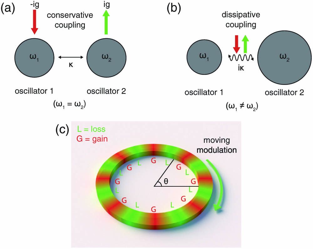
Based on the relationship between PT and APT symmetries, we derived how the bi-color lasing mode can be realized in an APT symmetric system. Typically, a PT symmetric system can be described by two oscillators with an identical resonance frequency, yet opposite damping factors. They are coupled through a conservative coupling process such as near field coupling [Fig. 1(a)]. In contrast, an APT system can be achieved by two oscillators with the same damping factor but different resonance frequencies. Those oscillators are coupled through purely dissipative channels such as far field coupling, as described in Fig. 1(b), satisfying . We leverage two whispering gallery modes (WGMs) in a micro-ring resonator to realize an APT system. To obtain a dissipative coupling component between two counter-propagating clockwise (CW) and counterclockwise (CCW) WGMs, we apply a moving grating with a sinusoidally modulated imaginary part of permittivity azimuthally along the micro-ring resonator [Fig. 1(c)]. The permittivity change can be expressed as , where is modulation depth, is an azimuthal modulation wavevector, is modulation frequency, and are azimuthal angle and time, respectively. This dynamic imaginary grating can be achieved through pumping the micro-ring resonator using the interference of two optical beams with slightly different center frequencies [26].
Figure 1.Schematic illustration of (a) PT and (b) APT symmetries in a two-oscillator system. (ig) and represent gain (loss) and coupling coefficients, respectively. In the PT symmetric system, resonance frequencies , of the two oscillators are identical, while they are different in the APT symmetric one. (c) Configuration of APT symmetric micro-ring resonator under spatiotemporal modulation for bi-color lasing. The dynamic imaginary grating of permittivity with alternating gain (G) and loss (L) is moving azimuthally along the ring. The moving direction is indicated by the green arrow.
To show that the system is APT symmetric, we analyze a pair of degenerated CW and CCW WGMs in the micro-ring cavity with a sinusoidal modulation profile. Assuming coupling exists only between these two modes with phase-matching and frequency-matching conditions, the eigenmodes of this system can be obtained by solving temporal coupled-mode equations [27]: where the time-dependent state vector and Hamiltonian of the system are written as
Here and are the amplitudes of the CW and CCW modes, respectively, is the original resonance frequency of the two WGMs, and is the time-varying coupling coefficient, where is proportional to the modulation depth of . It should be emphasized that can be either positive or negative in the Hamiltonian to indicate the modulation travels along CCW or CW direction, respectively. Taking the gauge transformation to remove the temporal variance, we get a time-independent :
We can see that the degeneracy between CW and CCW modes is broken in the new frame. The eigenvalues and the corresponding eigenvectors can be obtained: where . We note that the equation is solved under a gauge transformation , which means the solutions in Eq. (4) are eigenfrequencies in the moving frames of which the rotating frequencies are .
After changing back to the laboratory frame, The actual number of observable eigenfrequencies should be four in total, which are and .
Looking back into the time-independent Hamiltonian, it is evident that . Here the parity operator represents the mirror reflection given by the first Pauli matrix , which exchanges the spatial positions of these two optical modes, and the time-reversal operator is given by the complex conjugation. Therefore, we can verify that this system satisfies APT symmetry.
The dependence of real and imaginary parts of normalized with different coupling coefficients and temporal modulation frequencies is shown in Figs. 2(a) and 2(b), respectively. In both figures, the eigenfrequencies can be clearly classified into two regimes according to the existence of degeneracy. Taking a slice across both regimes [Fig. 2(c)], we can see that in the red regime, the real part is degenerate with a non-vanishing opposite imaginary part. In contrast, in the yellow regime, the real part splits with a zero imaginary part. The boundary of two regimes is along the line where [dashed lines in Figs. 2(a) and 2(b)]. Similar to those in PT symmetric systems, the eigenfrequency spectra in APT symmetric systems can transit from real to complex values. The transition boundaries are also called exceptional points (EPs) or exceptional lines (ELs). However, the properties of the corresponding eigenvectors are different between PT and APT symmetric cases. In a PT symmetric case, is satisfied in the regime where the eigenfrequency is complex. It is referred to as broken PT phase, as operating on do not lead to the same (). can be observed in the regime where eigenfrequency is purely real, which is referred to as unbroken PT phase. This behavior is opposite in our APT symmetric case: is satisfied in the regime where the eigenfrequency is complex (unbroken APT phase), while is fulfilled when the eigenfrequency is purely real (broken APT phase). In other words, both PT and APT symmetries have broken and unbroken phases, but the spectral properties of each phase are completely different. Moreover, does not merely define the boundary between the broken and unbroken APT phases in the solution of . It also contributes to the Doppler shift term , which determines the frequencies of modes in the laboratory frame (with respect to the moving frames under gauge transformation). Compared with the PT symmetry with only limited control over the phase transition, our APT system has additional degrees of freedom in manipulating spectral mode frequencies.
Figure 2.(a) Real and (b) imaginary parts of normalized eigenfrequency spectra with respect to modulation frequency and coupling coefficient . The black dashed lines are the exceptional lines, where the two eigenstates degenerate. (c) Real (solid lines) and imaginary parts (dashed lines) of eigenfrequencies under a fixed indicated by the gray planes in (a) and (b), respectively. The yellow and red regions indicate broken APT and unbroken APT phases, respectively. (d) Real and (e) imaginary parts of the eigenfrequencies versus with different (indicated by different colors). The red circles in (d) indicate the uncoupled cases (), and there are no sidebands. The red and blue curves are the modes in a PT symmetric case as reported in Ref. [15] for reference.
This spatiotemporal modulation enabled APT system with modes of opposite imaginary parts in the unbroken APT regime provides the foundation for creating our bi-color laser. In Fig. 2(c), the blue curve in the red region represents the mode of which the eigenfrequency has a negative imaginary part, indicating persistent amplification of the energy in this mode. With a sufficient large modulation depth , lasing from this mode is possible where the EP works as the lasing threshold since the mode begins to amplify beyond it towards the unbroken APT regime. Considering the frequency shifting term, two lasing modes with eigenfrequencies differing by can be observed in the system. Furthermore, if we assume the non-Hermitian coupling coefficient is much larger than , the corresponding eigenvector of both amplifying modes will be approximately. It indicates that the two lasing modes are actually the CW and CCW modes with broken degeneracy, respectively.
While we can get a only pair of degenerate CW and CCW lasing modes in a typical PT symmetric scheme since the real parts of their eigenfrequencies are identical, the dynamic modulation in our APT symmetric scheme enables frequency detuning of for those two lasing modes, respectively, in the unbroken APT phase. This property makes possible bi-color lasing in a single micro-ring cavity. Most importantly, those lasing modes propagate in opposite directions and hence are easy to separate spatially, which is not possible for conventional multi-mode lasers.
Considering and are separately determined by the spatiotemporal modulation depth and frequency, respectively, this APT system offers flexible control over the lasing properties. For example, the same phase transition process of can also be observed with determined and varying [Figs. 2(d) and 2(e)]. The EP position is shifted towards larger with larger . As the bi-color laser works only in the broken APT phase, the position of the EP can be effectively treated as an on–off switch for bi-color lasing operation. Since the EP is located at , both and determine the lasing threshold. Moreover, also tunes the frequency difference between two lasing modes.
3. MICRO-RING BI-COLOR DESIGN AND NUMERICAL VALIDATION
The unique features of our APT symmetry in the unbroken APT phase provide the theoretical keystone for realizing a demultiplexed multi-color laser. We chose realistic material parameters to construct our bi-color laser. Our micro-ring resonator consists of a semiconductor gain material, InGaAsP multi-quantum well (MQW), which sits on InP substrate. We kept the same sinusoidal profile of modulation as discussed in Section 2. The WGMs of different orders supported by the mirco-ring cavity are denoted by , where the positive and negative signs indicate CW and CCW modes, respectively. The mode number is an integer that can be calculated from , where is the perimeter of the micro-ring, is the effective index of the WGM, and is the free-space wavelength. We choose as two uncoupled modes and introduce the coupling through spatial phase-matching condition . In addition, we have the modulation frequency much smaller than the free spectral range (FSR) of the micro-ring to ensure that the coupling happens only between . Since is proportional to between the modes (see Appendix E for a detailed derivation), for the sake of simplicity, we use directly instead of in the following discussion.
We established a numerical model and conducted full-wave simulations of the proposed bi-color micro-ring laser using the finite difference time-domain (FDTD) method. The imaginary part of the permittivity of the micro-ring is spatiotemporally modulated in the azimuthal direction (see Appendix A for details of the model). To extract the lasing output, we used two straight waveguides evanescently coupled to the micro-ring in an add–drop configuration. With , , and spatiotemporal modulation frequency , the evolution of the resonances at different modulation depths can be observed in the normalized transmission and lasing spectra [Figs. 3(a) and 3(b)]. The definitions of the ports are depicted in the inset of Fig. 3. Without modulation, the signal enters the structure through the left-side waveguide from port 1 and couples to the CCW resonance, creating a dip in the transmission spectrum and a peak in the reflection spectrum around 1.555 μm.
Figure 3.(a) Normalized reflection spectra and lasing spectra , (b) normalized transmission spectra and lasing spectra under different modulation depths with a fixed modulation frequency (see Fig. 6 in Appendix B for and ). The definitions of the ports, , , , and are depicted in the insets. The yellow and red regimes indicate the broken and unbroken APT phases, respectively. (c) Real parts of the resonance frequencies and (d) imaginary parts of resonance wave vectors extracted from full-wave simulations (circles) and theoretical calculations based on the APT symmetry (dashed lines). The colors of the dashed curves in (c) and (d) correspond to the lines of the same color in (a) and (b).
Increasing the modulation depth of permittivity, a total of four resonances are clearly observed [Figs. 3(a) and 3(b)]. They can be classified into two categories in which the resonance frequencies differ by 1 THz (or 8 nm in terms of wavelength). In each category, the frequency difference between two resonances persistently reduces while increasing and finally becomes zero when . This indicates the phase transition across this point. In the red region, two amplified peaks are observed in the normalized spectra. We note that there is no signal input in this region. The numerically acquired resonance frequencies at different agree well with our prediction based on the APT symmetry theory across both yellow and red regions [Fig. 3(c)]. The small discrepancy is caused by the static backscattering induced by the mesh in our simulation model.
To further verify whether this change in spectra is indeed the phase transition between broken and unbroken APT phases, we obtained the imaginary parts of resonance wavevectors by fitting each spectrum with two Lorentz functions. The imaginary parts of the wavevectors then can be acquired through , where , , , and are the speed of light, refractive index of material, center wavelength, and linewidth of the resonance, respectively. The obtained values from simulations again match well with those calculated from the APT theory [Fig. 3(d)]. We can see that bifurcation occurs between two resonances in the imaginary spectrum in the red region, while they coalesce in the yellow region, which also matches well with our theoretical prediction, indicating the phase transition of APT symmetry. We also can see the linewidth of the resonance narrows when increasing the modulation depth before reaching the lasing threshold. Then it broadens again after passing the threshold. This phenomenon is due to the absolute value of the resonance frequency’s imaginary part decreasing with the modulation depth before reaching the lasing threshold and increasing after it [28]. Additionally, in our simulation, we noticed that is not zero at the EP. This is owed to the inherent loss in the system [Fig. 3(d)].
In the unbroken APT phase, two spectral lines separated by can be detected in all four ports. Lasing output at μ is observed at ports 2 and 4, which results from the CW mode; the μ laser line is observed at ports 1 and 3, which comes from the CCW mode [Figs. 4(a) and 4(b)]. Therefore, it is verified that two laser lines with different wavelengths can be generated simultaneously in a single micro-ring cavity and well separated inherently due to the directionality of the WGM modes. The bi-color lasing frequencies can be continuously tuned through varying the modulation frequency within [Fig. 4(c)]. In addition, the frequency tuning range for the bi-color lasing mode can be extended by increasing .
Figure 4.Normalized intensity distribution of the micro-ring system at (a) μ and (b) μ with and . The white lines outline the geometry of the micro-ring as well as the coupling waveguides. The white arrows indicate the traveling direction of spatiotemporal modulation, and the yellow arrows show the output lasing direction. The ports are numbered in the same way as those shown in Fig. 3. (c) Real parts of resonance frequencies extracted from full-wave simulations (circles) and the calculated ones based on our APT theory (dashed lines) with a fixed while varying . The red regime indicates the unbroken APT phase. (d) Lasing spectra from all ports with the same modulation depth as in (a) and (b). is the azimuthal order of the WGM.
Moreover, our APT-based laser significantly reduces unnecessary mode competition. In our micro-ring laser, only the desired WGMs () can be coupled to each other through dynamic modulation under a phase-matching condition (). The modulation frequency is smaller than FSR; hence, no coupling among neighboring WGMs was introduced. In addition, the dynamic modulation redistributes the optical gain such that it maximizes amplification for the desired mode while suppressing all other WGMs (Appendix F). Therefore, lasing from only the desired modes () can be achieved [Fig. 4(d)]. This reduction of mode competition improves the stability of bi-color lasing under various pumping conditions. We note that the discrepancy in lasing intensity between the two modes resulted from the coupling difference between the CCW and CW WGMs to the output waveguide induced by the geometry discretization of the micro-ring in our simulation.
In addition to the laser operation we demonstrated in unbroken APT phase, nonreciprocal light propagation can be observed in the broken APT phase of our system. The temporal modulation of permittivity shifts the resonances oppositely for CW and CCW modes and breaks the reciprocity of the system. This can be verified by comparing the transmission spectra and at different input ports (Appendix E). This nonreciprocal behavior in the broken APT regime could lead to realization of other useful optical elements such as an optical isolator.
4. DISCUSSION ON EXPERIMENTAL REALIZATION
In practice, azimuthal spatiotemporal modulation can be realized by interference between two laser pump beams of different frequencies carrying different orbital angular momenta (OAMs). The imprinted vortex phase front of different OAM orders will provide the required . In the past, we have achieved spatiotemporal modulation of the real part of permittivity along a straight line using a similar technique, where we used two laser pump beams with slightly different frequencies to generate a traveling wave interference pattern [26,29]. The temporal modulation frequency can easily reach up to several terahertz by exploiting the instantaneous third-order nonlinear response of material [30]. However, the maximum modulation speed of gain is limited by the relaxation time of the excited carriers in the material, which is typically around nanosecond scale in semiconductors. Hence, the largest modulation frequency achievable for gain is in the gigahertz range. To have higher modulation frequency, a feasible solution is to apply a spatiotemporal loss modulation instead of gain modulation with materials of ultrafast response. For example, the relaxation time of carriers in graphene can be as short as several hundreds of femtoseconds [31], and tuning the loss of graphene under optical pumping has already been utilized for ultrafast optical modulators [32]. Therefore, we envision that by placing thin layers of graphene on top of our optical structures, we can effectively modulate the imaginary part of the permittivity at a high frequency.
5. CONCLUSION
In conclusion, we theoretically proposed and numerically validated an APT symmetric bi-color laser enabled by spatiotemporal modulation of gain/loss distribution in a micro-ring resonator. Tunable modulation frequency and modulation depth provide two degrees of freedom for real-time manipulation of the lasing dynamics. This APT-symmetry-enabled bi-color lasing scheme can be generalized to multi-color cases with more than two lasing modes. Exploiting the non-Hermitian symmetries in optical systems, we can expect the revolution of current lasers in terms of functionality, stability, size, etc., which could enable a plethora of applications such as on-chip coherent light sources for communications, remote sensing, and displays.
APPENDIX A. SIMULATION MODEL OF TIME-VARYING STRUCTURE
The micro-ring bi-color laser model with dynamic modulation was established in Lumerical FDTD software. The time-varying permittivity was realized by a customized material plug-in. Compared with modulation of the real part of permittivity, manipulation of only the imaginary part was difficult since we could not directly assign an imaginary number to variables in the material plug-in. A viable way is to use the Lorentz model with well-tuned parameters. Therefore, the modulation of permittivity can be written as
Here is the center resonance frequency, and is the damping coefficient of the material. is the frequency of a wave traveling through the medium, and , , are modulation frequency, modulation wave vector, and modulation phase, respectively. is the modulation depth that we can tune during simulation. To get almost a pure imaginary part modulation, we first set around the scale of simulation frequency ( for 1.555?μm) and . However, the simulation process was quite unstable, and no dynamic modulation effect was observed if . Therefore, we reduced and kept it slightly larger than with and . With , the time-independent around 1.55?μm is shown in Fig.?5. The imaginary part is almost 100 times larger than the real part, which can approximately be viewed as the modulation of the imaginary part only. But the influence of a tiny residue real part modulation on eigenmode frequencies cannot be fully eliminated, which is manifested as small but persistent drift of all resonance curves under increasing modulation depth, as shown in Figs.?3(a)–3(c).
Figure 5.Real and imaginary parts of around 1.55 μm under and . The imaginary part is around 100 times larger than the real part.
APPENDIX B. DEVIATION OF TRANSMISSION SPECTRA FROM THEORETICAL PREDICTION
The theoretical prediction deviated a little bit from the simulation result when (Fig.?3), because there was competition between the dynamic coupling and static backscattering process induced by the simulation grid. The static backscattering was weak but dominant when the modulation was small, which would shift the resonances slightly.
In Figs.?6(a) and 6(b), we also notice that the second resonance cannot be observed in , while looks almost the same as in Fig.?3(a). Since we used a short input pulse whose length was less than the perimeter of the ring in the simulation, the field was unevenly distributed inside the ring. The sideband did not get much energy converted from the main resonance owing to a short propagation length in the first half-cycle along the ring. The energy coupled out into the drop waveguide was very small. Then the sideband accumulated enough energy from the last half-cycle but most was coupled out into the input bus waveguide. Therefore, we could see a sideband peak in but not in .
Figure 6.(a) Numerical normalized transmission spectra , lasing spectra , (b) transmission spectra , and lasing spectra under different modulation depths and . The definitions of , , , and are depicted in the inset. The yellow and red shaded areas indicate different APT phases.
APPENDIX C. TRANSMISSION SPECTRA OVER DIFFERENT MODULATION FREQUENCIES
Figures?3 and 6 show the reflection and transmission spectra over different modulation depths. Based on Eq.?(4), increasing the modulation frequency from zero will result in the phase transition from unbroken APT phase to broken APT phase. This trend can be verified in Figs.?4 and 7. In Fig.?7, all the spectra start from one lasing peak and bifurcate into two converging resonance peaks (or dips) under increasing . The frequency difference between two resonances increases with larger . At the same time, the amplitude of the second resonance reduces owing to the deviation from the center frequency of the original WGM resonance, which will result in a larger phase mismatch. If we record the resonance position and plot the dependence of resonance wavelength with , they also fit well with APT theory as in Fig.?4(c).
Figure 7.Simulated transmission spectra from to and lasing spectra from to under increasing modulation frequency. Modulation depth . The circles mark the spectral position of the resonances. The red regime indicates unbroken APT phase.
APPENDIX D. EFFECTIVE MODULATION DEPTH FROM STEPWISE SIMULATION
To apply spatiotemporal modulation on the micro-ring in simulation, the assumption of continuous modulation can be approximated only by discretized blocks. The permittivity of these blocks differs coherently by a fixed phase shift along the ring to represent the spatial variation. If the ring is discretized into blocks in total along the ring, the modulation can be expressed as where is a rectangular function with unitary height and width centered at zero. is modulation strength. , , , and have the same definition as in Eq.?(A1). is the angular width of a single block, and is the angular position of the center of the th block. Based on Poisson summation, it can be expanded as [33] where , and is an integer. Therefore, a discretized stepwise permittivity profile can be decomposed into a combination of sinusoidal modulation with the same modulation frequency but different wave vectors. Considering the phase match condition, only the one satisfying can resonantly introduce dynamic coupling between . The effective modulation depth can be computed as
In our simulation, , , with , , and . Moreover, the actual modulation depth of the imaginary part should also consider the modulation depth of the Lorentz model in the material plug-in, which is around 1.55?μm. Considering all of these, we can get . Therefore, the sinusoidal modulation can be well approximated by a stepwise modulation model that differs only by a constant factor.
APPENDIX E. THEORETICAL CALCULATION OF NONRECIPROCAL TRANSMISSION SPECTRA
Here we take the bypass configuration with only one bus waveguide for simplicity. We assume the electric field amplitudes of (CW) and (CCW) modes are and , respectively. The resonance frequency is . The time-independent coupling coefficients and can be computed by the electric field overlapping between two modes, which is . In a single-mode waveguide, the spatial mode profile across the cross section is the same for . Thus, we can reduce the coupling coefficient expression to [34]. Here is the permittivity of the medium without modulation.
Incorporating the excitation from the bus waveguide, the coupled mode equations are
Here and are field amplitudes of excitation from port 1 and port 2. is the modulation frequency. are evanescent coupling coefficients between the bus waveguide and modes. is the total loss factor including coupling, scattering, and radiation loss.
The output field transmission coefficient from port 1 () and port 2 () can be expressed as where and are coupling phases. With all the equations above, the normalized transmission spectra with excitation from different ports are solved as where indicates the complex resonance frequency. The calculated curves based on coupled mode theory fit the simulation result well in broken APT phase as depicted in Fig.?8. The resonances are shifted oppositely with excitation from different ports. Considering the existence of temporal modulation, this system is indeed nonreciprocal in broken APT phase.
Figure 8.Transmission spectra and around resonance in broken APT phase. The micro-ring diameter is smaller than the one in the main text. The crosses are simulation results under three different , and the curves are theoretical calculation from Eqs. (E5) and (E6). Here is the modulation depth at EP.
APPENDIX F. TEMPORAL FIELD EVOLUTION IN DIFFERENT APT PHASE
The single-mode APT symmetry lasing mechanism can be further explained by temporal field evolution inside a micro-ring cavity. Interference patterns of excited by a pulse around 1550?nm in broken APT phase are shown in Figs.?9(a)–9(c). The intensity profile is not azimuthally uniform along the ring and decays gradually. Within one modulation period , the movement of intensity maxima is not synchronized with the motion of the modulation profile. The field maxima travel across both gain and loss regions without any preference of staying in one region compared with the other. Adding the inherent loss of the system, the time-averaged energy dissipation rate will be lossy, and the field intensity is observed to decay gradually. As a comparison, the field movement in unbroken APT phase is synchronized with the evolution of modulation, as depicted in Figs.?9(d)–9(f). The field localized in the gain region will be consistently amplified and finally contribute to the lasing in the micro-ring. It is worth mentioning that this works only when the number of field maxima exactly equals the period of modulation along the micro-ring. Any deviation from this equality will reduce overlapping between the gain region and field intensity, leading to a larger lasing threshold. With reasonable pumping intensity, the lasing can be controlled within a single mode without any disturbance from other longitudinal modes, which explains what we observe in Fig.?4(d).
Figure 9.Intensity distribution at different times in (a)–(c) broken APT phase and (d)–(f) unbroken APT phase for . The modulation propagates counterclockwise with frequency of . (a), (d) Intensity profile at ; (b), (e) at ; (c), (f) at . Here , are reference time and the period of spatiotemporal modulation (), respectively. Insets show zoom-in view of the interference patterns and modulation profile in the blue dashed box. The red and yellow arrows indicate the traveling directions of both modulation and intensity profiles, respectively. The black arrow and black dashed lines mark the full width at half maximum of the intensity profile.
[1] C. A. Brackett. Dense wavelength division multiplexing networks: principles and applications. IEEE J. Sel. Areas Commun., 8, 948-964(1990).
[2] R. Dändliker, R. Thalmann, D. Prongué. Two-wavelength laser interferometry using superheterodyne detection. Opt. Lett., 13, 339-341(1988).
[3] J. Zhao, Y. Yan, Z. Gao, Y. Du, H. Dong, J. Yao, Y. S. Zhao. Full-color laser displays based on organic printed microlaser arrays. Nat. Commun., 10, 1(2019).
[4] Y. Ding, Q. Yang, X. Guo, S. Wang, F. Gu, J. Fu, Q. Wan, J. Cheng, L. Tong. Nanowires/microfiber hybrid structure multicolor laser. Opt. Express, 17, 21813-21818(2009).
[5] F. Fan, S. Turkdogan, Z. Liu, D. Shelhammer, C.-Z. Ning. A monolithic white laser. Nat. Nanotechnol., 10, 796-803(2015).
[6] R.-M. Ma, X. Yin, R. F. Oulton, V. J. Sorger, X. Zhang. Multiplexed and electrically modulated plasmon laser circuit. Nano Lett., 12, 5396-5402(2012).
[7] P. Dekker, M. Ams, T. Calmano, S. Gross, C. Kränkel, G. Huber, M. Withford. Spectral narrowing of Yb:YAG waveguide lasers through hybrid integration with ultrafast laser written Bragg gratings. Opt. Express, 23, 20195-20202(2015).
[8] X. Hu, G. Zhao, Z. Yan, X. Wang, Z. Gao, H. Liu, J. He, S. Zhu. High-power red-green-blue laser light source based on intermittent oscillating dual-wavelength Nd:YAG laser with a cascaded LiTaO3 superlattice. Opt. Lett., 33, 408-410(2008).
[9] Y. Fujimoto, O. Ishii, M. Yamazaki. Multi-colour laser oscillation in Pr3+-doped fluoro-aluminate glass fibre pumped by 442.6 nm GaN-semiconductor laser. Electron. Lett., 45, 1301-1302(2009).
[10] D. Wang, A. Yang, W. Wang, Y. Hua, R. D. Schaller, G. C. Schatz, T. W. Odom. Band-edge engineering for controlled multi-modal nanolasing in plasmonic superlattices. Nat. Nanotechnol., 12, 889-894(2017).
[11] S. T. Ha, Y. H. Fu, N. K. Emani, Z. Pan, R. M. Bakker, R. Paniagua-Domnguez, A. I. Kuznetsov. Directional lasing in resonant semiconductor nanoantenna arrays. Nat. Nanotechnol., 13, 1042-1047(2018).
[12] C. M. Bender, S. Boettcher. Real spectra in non-Hermitian Hamiltonians having PT symmetry. Phys. Rev. Lett., 80, 5243-5246(1998).
[13] C. E. Rüter, K. G. Makris, R. El-Ganainy, D. N. Christodoulides, M. Segev, D. Kip. Observation of parity–time symmetry in optics. Nat. Phys., 6, 192-195(2010).
[14] B. Peng, Ş. Özdemir, S. Rotter, H. Yilmaz, M. Liertzer, F. Monifi, C. Bender, F. Nori, L. Yang. Loss-induced suppression and revival of lasing. Science, 346, 328-332(2014).
[15] L. Feng, Z. J. Wong, R.-M. Ma, Y. Wang, X. Zhang. Single-mode laser by parity-time symmetry breaking. Science, 346, 972-975(2014).
[16] P. Miao, Z. Zhang, J. Sun, W. Walasik, S. Longhi, N. M. Litchinitser, L. Feng. Orbital angular momentum microlaser. Science, 353, 464-467(2016).
[17] H. Zhao, X. Qiao, T. Wu, B. Midya, S. Longhi, L. Feng. Non-Hermitian topological light steering. Science, 365, 1163-1166(2019).
[18] L. Ge, H. E. Türeci. Antisymmetric PT-photonic structures with balanced positive- and negative-index materials. Phys. Rev. A, 88, 053810(2013).
[19] P. Peng, W. Cao, C. Shen, W. Qu, J. Wen, L. Jiang, Y. Xiao. Anti-parity–time symmetry with flying atoms. Nat. Phys., 12, 1139-1145(2016).
[20] Y. Li, Y.-G. Peng, L. Han, M.-A. Miri, W. Li, M. Xiao, X.-F. Zhu, J. Zhao, A. Alù, S. Fan, C. W. Qiu. Anti-parity-time symmetry in diffusive systems. Science, 364, 170-173(2019).
[21] Y. Choi, C. Hahn, J. W. Yoon, S. H. Song. Observation of an anti-PT-symmetric exceptional point and energy-difference conserving dynamics in electrical circuit resonators. Nat. Commun., 9, 2182(2018).
[22] F. Zhang, Y. Feng, L. Ge, W. Wan. Synthetic parity-time symmetry breaking in a single microcavity(2019).
[23] H. Fan, J. Chen, Z. Zhao, J. Wen, Y. Huang. Anti-parity-time symmetry in passive nanophotonics(2020).
[24] X.-L. Zhang, T. Jiang, C. T. Chan. Dynamically encircling an exceptional point in anti-parity-time symmetric systems: asymmetric mode switching for symmetry-broken modes. Light Sci. Appl., 8, 1(2019).
[25] H. Zhang, R. Huang, S.-D. Zhang, Y. Li, C.-W. Qiu, F. Nori, H. Jing. Breaking anti-PT symmetry by spinning a resonator. Nano Lett., 20, 7594-7599(2020).
[26] X. Guo, Y. Ding, Y. Duan, X. Ni. Nonreciprocal metasurface with space–time phase modulation. Light Sci. Appl., 8, 123(2019).
[27] W. Suh, Z. Wang, S. Fan. Temporal coupled-mode theory and the presence of non-orthogonal modes in lossless multimode cavities. IEEE J. Quantum Electron., 40, 1511-1518(2004).
[28] M. Pollnau, M. Eichhorn. Spectral coherence, part I: passive-resonator linewidth, fundamental laser linewidth, and Schawlow-Townes approximation. Prog. Quantum Electron., 72, 100255(2020).
[29] J. Leach, A. Wright, J. Götte, J. Girkin, L. Allen, S. Franke-Arnold, S. Barnett, M. Padgett. “Aether drag” and moving images. Phys. Rev. Lett., 100, 153902(2008).
[30] R. Righini. Ultrafast optical Kerr effect in liquids and solids. Science, 262, 1386-1390(1993).
[31] J. M. Dawlaty, S. Shivaraman, M. Chandrashekhar, F. Rana, M. G. Spencer. Measurement of ultrafast carrier dynamics in epitaxial graphene. Appl. Phys. Lett., 92, 042116(2008).
[32] W. Li, B. Chen, C. Meng, W. Fang, Y. Xiao, X. Li, Z. Hu, Y. Xu, L. Tong, H. Wang, W. Liu, J. Bao, Y. R. Shen. Ultrafast all-optical graphene modulator. Nano Lett., 14, 955-959(2014).
[33] D. L. Sounas, A. Alù. Angular-momentum-biased nanorings to realize magnetic-free integrated optical isolation. ACS Photon., 1, 198-204(2014).
[34] D. L. Sounas, C. Caloz, A. Alù. Giant non-reciprocity at the subwavelength scale using angular momentum-biased metamaterials. Nat. Commun., 4, 2407(2013).