• Chinese Optics Letters
  • Vol. 15, Issue 8, 081101 (2017)
Lingjun Kong1, Rui Liu1, Yu Si1, Zhouxiang Wang1, Chenghou Tu1, Yongnan Li1、*, and Huitian Wang1、2、3
Author Affiliations
  • 1MOE Key Laboratory of Weak Light Nonlinear Photonics and School of Physics, Nankai University, Tianjin 300071, China
  • 2National Laboratory of Solid State Microstructures and School of Physics, Nanjing University, Nanjing 210093, China
  • 3Collaborative Innovation Center of Advanced Microstructures, Nanjing University, Nanjing 210093, China
  • show less
    DOI: 10.3788/COL201715.081101 Cite this Article Set citation alerts
    Lingjun Kong, Rui Liu, Yu Si, Zhouxiang Wang, Chenghou Tu, Yongnan Li, Huitian Wang. Time-resolved multiple imaging by detecting photons with changeable wavelengths[J]. Chinese Optics Letters, 2017, 15(8): 081101 Copy Citation Text show less
    Experimental setup for time-resolved multiple imaging with undetected photons. The light source is a fs pulsed light source at a central wavelength of 810 nm with a pulse duration of ∼140 fs and a repetition rate of ∼80 MHz (the interval between two pulses is ∼12.5 ns). Two BBO crystals are used to realize the wavelength conversion. The process of second-harmonic generation happening in BBO1 will transform the wavelength from 810 to 405 nm. SPDC occurs in BBO2 and transforms the wavelength from 405 nm to the one that we need. DMs are used to remove the unwanted light. Here, DM1 transmits 405 nm light (96%) and reflects 810 nm light (97%). The other dichotic mirrors reflect 405 nm light (96%). There are three objects. O1 is letter “N”, O2 is letter “K”, and O3 is letter “U”. Plane “1” is the object plane; plane “2”, plane “3”, and plane “3′” are the image planes of the object. (a) The scanning imaging system arrangement, where the detector D2 needs to scan step by step to reconstruct the images of the objects. (b) The imaging with the ICCD and the image preserving delay compensation system arrangement. Insert: Rotation of BBO2 to generate the photons with the needed wavelength from SPDC. When α=0.75°, photons with a 1064 nm wavelength can be collected by D2. When α=1.04°, the wavelength of photons that we can collect is 650 nm. Inset: Measurement of the time-resolved correlation of the fs pulsed laser used, experimental data (blue symbols) and Gaussian fitting profile (red curve).
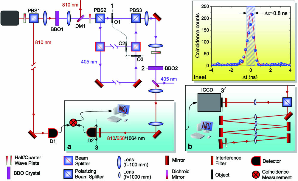
    Fig. 1. Experimental setup for time-resolved multiple imaging with undetected photons. The light source is a fs pulsed light source at a central wavelength of 810 nm with a pulse duration of 140fs and a repetition rate of 80MHz (the interval between two pulses is 12.5ns). Two BBO crystals are used to realize the wavelength conversion. The process of second-harmonic generation happening in BBO1 will transform the wavelength from 810 to 405 nm. SPDC occurs in BBO2 and transforms the wavelength from 405 nm to the one that we need. DMs are used to remove the unwanted light. Here, DM1 transmits 405 nm light (96%) and reflects 810 nm light (97%). The other dichotic mirrors reflect 405 nm light (96%). There are three objects. O1 is letter “N”, O2 is letter “K”, and O3 is letter “U”. Plane “1” is the object plane; plane “2”, plane “3”, and plane “3” are the image planes of the object. (a) The scanning imaging system arrangement, where the detector D2 needs to scan step by step to reconstruct the images of the objects. (b) The imaging with the ICCD and the image preserving delay compensation system arrangement. Insert: Rotation of BBO2 to generate the photons with the needed wavelength from SPDC. When α=0.75°, photons with a 1064 nm wavelength can be collected by D2. When α=1.04°, the wavelength of photons that we can collect is 650 nm. Inset: Measurement of the time-resolved correlation of the fs pulsed laser used, experimental data (blue symbols) and Gaussian fitting profile (red curve).
    (Color online) Experimental results. (a) is an example of coincidence measurement between detector D1 and D2 for the scanning imaging system arrangement. (b1), (b2), and (b3) are images of the three objects reconstructed from the coincidence measurement. 40×40=1600 scanning steps are needed. Measurement time is about 5 seconds for each step. (b4) is a mixed image of the three objects achieved by extracting all information containing in the three peaks at each scanning step. (c1), (c2), and (c3) are images of the three objects by using the ICCD and image preserving delay compensation system arrangement. (c4) is the mixed image of the three objects recorded by triggering the ICCD with an internal pulse generator. (d) The red circles and the blue circles are the partial data of (b1) (along the red line) and (c1) (along the dark blue line), respectively, and the red and blue curves are the fitting results corresponding to the data shown by the red and blue circles.
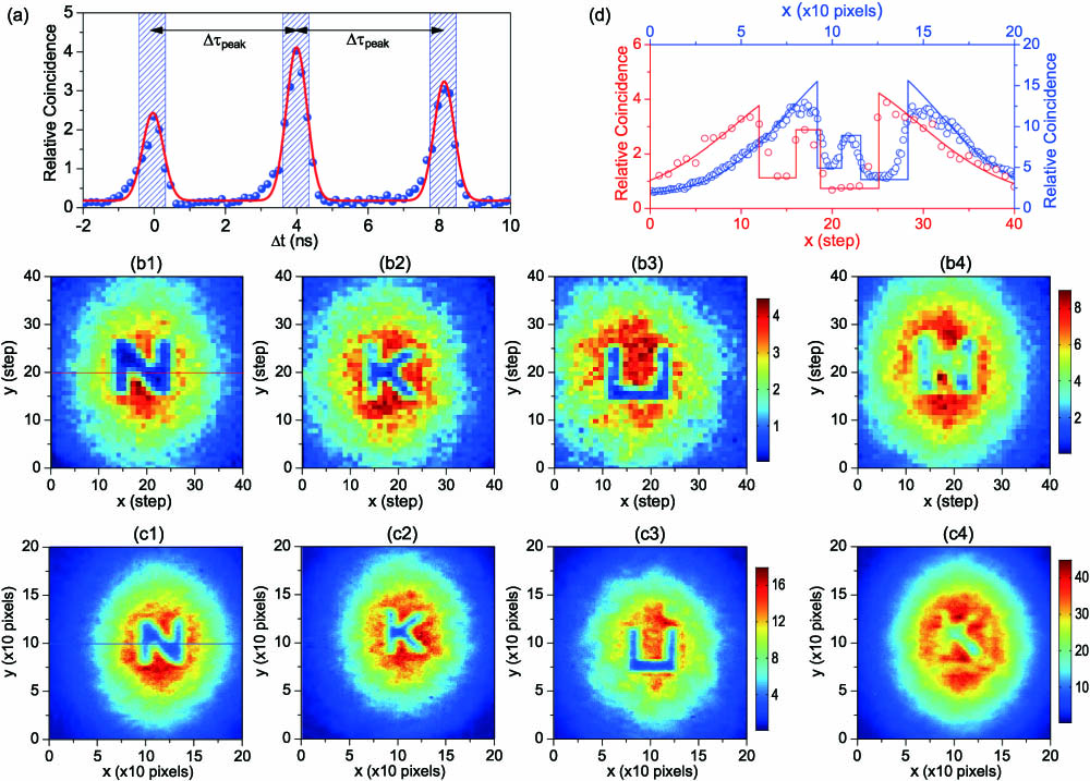
    Fig. 2. (Color online) Experimental results. (a) is an example of coincidence measurement between detector D1 and D2 for the scanning imaging system arrangement. (b1), (b2), and (b3) are images of the three objects reconstructed from the coincidence measurement. 40×40=1600 scanning steps are needed. Measurement time is about 5 seconds for each step. (b4) is a mixed image of the three objects achieved by extracting all information containing in the three peaks at each scanning step. (c1), (c2), and (c3) are images of the three objects by using the ICCD and image preserving delay compensation system arrangement. (c4) is the mixed image of the three objects recorded by triggering the ICCD with an internal pulse generator. (d) The red circles and the blue circles are the partial data of (b1) (along the red line) and (c1) (along the dark blue line), respectively, and the red and blue curves are the fitting results corresponding to the data shown by the red and blue circles.
    (Color online) Experimental results. (a1), (a2), and (a3) are images of the three objects reconstructed by detecting photons at 650 nm with the same dimension of 40×40 scanning steps, and the measurement time is ∼5 s for each step. (b1), (b2), and (b3) are images of the three objects by using the ICCD arrangement at 650 nm with a dimension of 200×200 pixels corresponding to an area of 2.6×2.6 mm2. (c1), (c2), and (c3) are images of the three objects reconstructed by detecting photons at 1064 nm with the same dimension of 40×40 scanning steps, and the measurement time is ∼5 s for each step.
    Fig. 3. (Color online) Experimental results. (a1), (a2), and (a3) are images of the three objects reconstructed by detecting photons at 650 nm with the same dimension of 40×40 scanning steps, and the measurement time is 5s for each step. (b1), (b2), and (b3) are images of the three objects by using the ICCD arrangement at 650 nm with a dimension of 200×200pixels corresponding to an area of 2.6×2.6mm2. (c1), (c2), and (c3) are images of the three objects reconstructed by detecting photons at 1064 nm with the same dimension of 40×40 scanning steps, and the measurement time is 5s for each step.
    Lingjun Kong, Rui Liu, Yu Si, Zhouxiang Wang, Chenghou Tu, Yongnan Li, Huitian Wang. Time-resolved multiple imaging by detecting photons with changeable wavelengths[J]. Chinese Optics Letters, 2017, 15(8): 081101
    Download Citation