• Chinese Physics B
  • Vol. 29, Issue 9, (2020)
Da-Hui Qin, Yun-Fei Duan, Dong Cheng, Ming-Zhu Su, and Yong-Bo Shao
Author Affiliations
  • School of Civil Engineering and Geomatics, Southwest Petroleum University, Chengdu 610500, China
  • show less
    DOI: 10.1088/1674-1056/abad1b Cite this Article
    Da-Hui Qin, Yun-Fei Duan, Dong Cheng, Ming-Zhu Su, Yong-Bo Shao. An extended cellular automata model with modified floor field for evacuation[J]. Chinese Physics B, 2020, 29(9): Copy Citation Text show less
    Schematic diagram of the von Neumann neighborhood (left) and Moore neighborhood (right). The gray cells indicate the corresponding neighbors of the central cell.
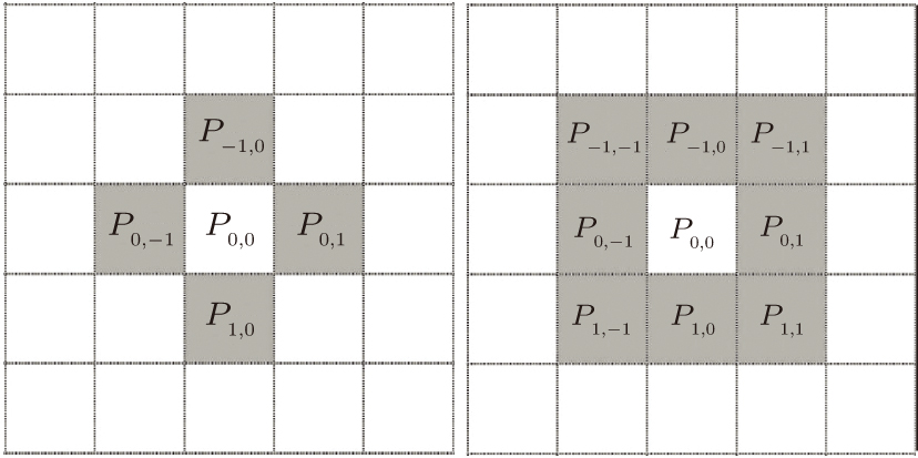
    Fig. 1. Schematic diagram of the von Neumann neighborhood (left) and Moore neighborhood (right). The gray cells indicate the corresponding neighbors of the central cell.
    Schematic diagram of the modified floor field. The gray cells represent the cells occupied by walls or obstacles, the red line represents the exit centerline, and the black frame area represents the hypothetical exit area Z. The exit area Z is divided into two equal areas A and B by the exit centerline.
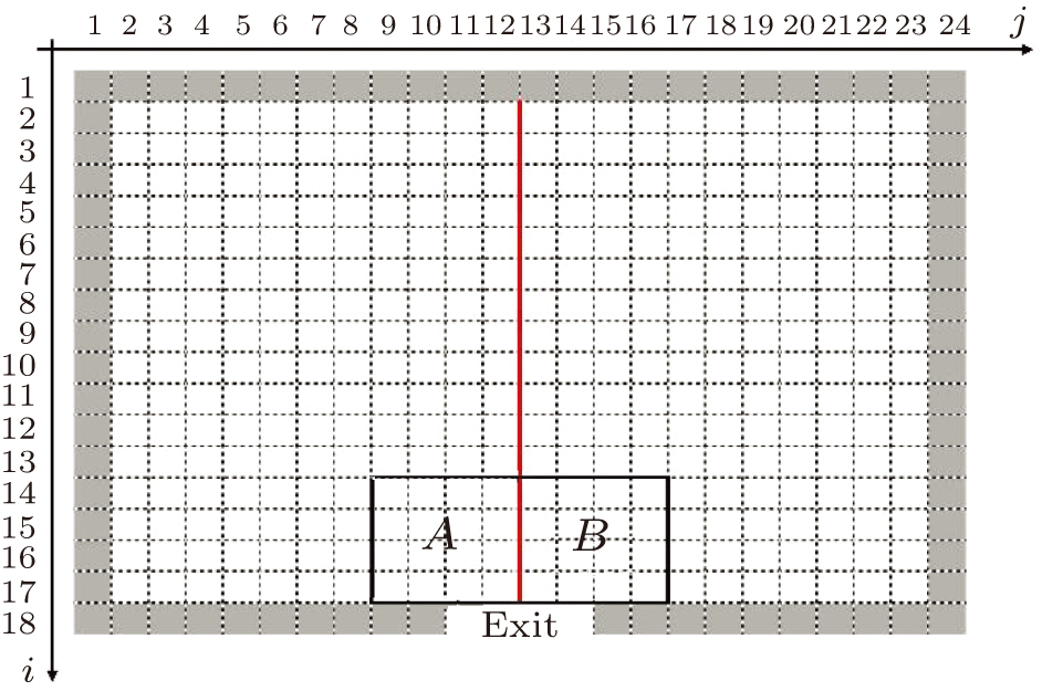
    Fig. 2. Schematic diagram of the modified floor field. The gray cells represent the cells occupied by walls or obstacles, the red line represents the exit centerline, and the black frame area represents the hypothetical exit area Z. The exit area Z is divided into two equal areas A and B by the exit centerline.
    Schematic diagram of the experimental scenario. The black cells are occupied by walls or obstacles, gray cells are occupied by pedestrians, and A and B are two different exits.
    Fig. 3. Schematic diagram of the experimental scenario. The black cells are occupied by walls or obstacles, gray cells are occupied by pedestrians, and A and B are two different exits.
    Effect of KC on the evacuation time of two exits. Last_A and last_B respectively indicate the time when the last person evacuated exits A and B with different KC. Evacuation time is the larger value between last_A and last_B with the same KC.
    Fig. 4. Effect of KC on the evacuation time of two exits. Last_A and last_B respectively indicate the time when the last person evacuated exits A and B with different KC. Evacuation time is the larger value between last_A and last_B with the same KC.
    Effect of KC on the number of people evacuated through two exits. Number_A and number_B respectively represent the number of people using exit A and exit B to evacuate.
    Fig. 5. Effect of KC on the number of people evacuated through two exits. Number_A and number_B respectively represent the number of people using exit A and exit B to evacuate.
    Effect of KC on evacuation time under different numbers of people T.
    Fig. 6. Effect of KC on evacuation time under different numbers of people T.
    Effect of KR on the evacuation time of two exits. Last_A and last_B respectively indicate the time when the last person evacuated exits A and B with different KR. Evacuation time is the larger value between last_A and last_B with the same KR.
    Fig. 7. Effect of KR on the evacuation time of two exits. Last_A and last_B respectively indicate the time when the last person evacuated exits A and B with different KR. Evacuation time is the larger value between last_A and last_B with the same KR.
    Space usage intensity map of the model without MFF.
    Fig. 8. Space usage intensity map of the model without MFF.
    Space usage intensity map of the model with MFF.
    Fig. 9. Space usage intensity map of the model with MFF.
    Space usage intensity map of Pathfinder.
    Fig. 10. Space usage intensity map of Pathfinder.
    Screenshot of the simulation process of the conventional CA model. Each gray dot in the picture represents a person. Screenshot time is after the start of simulation: panels (a), (b), (c), (d), (e), (f), (g), and (h) denote 0 s, 15 s, 30 s, 45 s, 60 s, 75 s, 90 s, and 115 s, respectively.
    Fig. 11. Screenshot of the simulation process of the conventional CA model. Each gray dot in the picture represents a person. Screenshot time is after the start of simulation: panels (a), (b), (c), (d), (e), (f), (g), and (h) denote 0 s, 15 s, 30 s, 45 s, 60 s, 75 s, 90 s, and 115 s, respectively.
    Screenshot of the simulation process of the improved CA model with MFF. Each gray dot in the picture represents a person. Screenshot time is after the start of simulation: panels (a), (b), (c), (d), (e), (f), (g), and (h) denote 0 s, 15 s, 30 s, 45 s, 60 s, 75 s, 90 s, and 115 s, respectively.
    Fig. 12. Screenshot of the simulation process of the improved CA model with MFF. Each gray dot in the picture represents a person. Screenshot time is after the start of simulation: panels (a), (b), (c), (d), (e), (f), (g), and (h) denote 0 s, 15 s, 30 s, 45 s, 60 s, 75 s, 90 s, and 115 s, respectively.
    ModelNumber of evacuated persons at different exitsTime consumed/s
    Exit AExit B
    CA model without MFF164.98123.0274.16
    CA model with MFF158.70129.3066.96
    Pathfinder14114773.8
    Table 1. Results of the evacuation simulation of the three models.
    Da-Hui Qin, Yun-Fei Duan, Dong Cheng, Ming-Zhu Su, Yong-Bo Shao. An extended cellular automata model with modified floor field for evacuation[J]. Chinese Physics B, 2020, 29(9):
    Download Citation