1School of Optical and Electronic Information, National Engineering Laboratory for Next Generation Internet Access System, Huazhong University of Science and Technology, Wuhan 430074, China
2Aston Institute of Photonic Technologies, Aston University, Birmingham B4 7ET, UK
Xi Guo, Zhikun Xing, Huabao Qin, Qizhen Sun, Deming Liu, Lin Zhang, Zhijun Yan, "Study on polarization spectrum and annealing properties of 45°-tilted fiber gratings," Chin. Opt. Lett. 17, 050601 (2019)
Copy Citation Text
We have investigated the whole polarization-extinction-ratio (PER) spectrum and annealing properties of 45°-tilted fiber gratings (45°-TFGs). Experimental results show the PER spectrum of 45°-TFGs is a Gaussian-like profile and covers a 540 nm bandwidth from 1260 to 1800 nm, in which the bandwidth with PER greater than 10 dB is over 250 nm. The output polarization distribution of 45°-TFGs was analyzed by employing a bulk linear polarizer, and the results show a perfect figure “8”, which indicates that the 45°-TFG is a type of linear polarizer. Moreover, the annealing property of 45°-TFGs was measured up to 700°C, in which the PER of the grating started to decrease at 300°C and reached the minimum at 700°C. Based on these results, the 45°-TFGs can be used as an ultra-wide bandwidth in-fiber polarizing device.
The 45°-tilted fiber grating (45°-TFG), which can filter out s polarization (TE) from the forward propagating core mode, while the residual p-polarized light (TM) propagates along the fiber core, has great potential as an ideal in-fiber polarizer for applications in optical communication, sensor, and laser systems. Compared with the traditional polarizing devices, the 45°-TFG contains a number of prominent merits, including high polarization-extinction-ratio (PER), low insertion loss, compact structure, good heat dissipation, simple fabrication method, and nice compatibility with standard fiber devices, which make the 45°-TFG more desirable for modern all-fiber systems. Since the first TFG structure was reported by Meltz in 1990[1], the TFGs have aroused researchers’ interests, and many theoretical researches based on TFGs have been undertaken in succession[2–4]. However, the fabrication methods limited the development and application of TFGs. Benefiting from the UV inscription technique, which made the bulk production of TFGs more viable, the TFGs were extensively investigated and found to have good polarization properties when the tilted angle is exactly 45° with respect to the normal of the fiber axis. Then, various applications based on 45°-TFGs were achieved, such as an in-fiber polarizer[5], in-fiber polarimeter[6], PER equalizer[7], and interference filter[8]. Apart from the applications in polarizing devices, the 45°-TFGs were also implemented as in-fiber diffraction gratings in the communication and imaging systems[9–12]. At present, the main applications of 45°-TFGs are focused on the all-fiber ultrafast mode-locked laser systems[13–18]. One of the major achievements is a mode-locked pulse in a wide wavelength range[16], which has been realized due to the considerably broad bandwidth of 45°-TFGs. However, there is no report on comprehensive analysis about the whole PER spectrum of 45°-TFGs, which is essential for further development towards real applications.
Nowadays, optical fiber devices are desirable for many harsh environmental applications[19–21], especially in a high-temperature environment, such as the oil and gas industries[22] and the monitoring of engine turbines and furnaces[23]. In view of these requirements, annealing properties are of much significance in determining the performance in high-temperature applications. However, no systematic study concerning the high-temperature characteristics of 45°-TFGs has been published yet. In this Letter, we will experimentally investigate the whole PER spectrum of the 45°-TFG, output polarization distribution, and its high-temperature annealing properties.
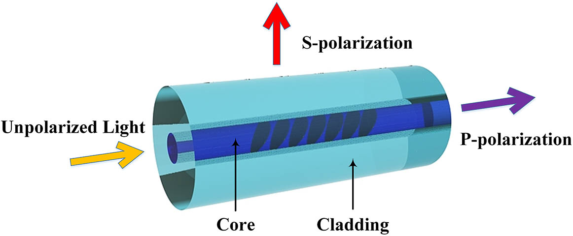
The principle of 45°-TFGs can be explained clearly with Brewster’s law. As we know, the light incident at Brewster’s angle on an optical interface will partially cease its TE component. In a typical UV-inscribed fiber grating, the Brewster’s angle can be given as[24]where and are the refractive indices of the fiber core and UV-induced refractive index modulation, respectively. Because () is far less than , the Brewster’s angle for the fiber grating is calculated to be . Therefore, as depicted in Fig. 1, when unpolarized light propagates through a 45°-TFG, the s-polarized light will be coupled out from the side of the fiber, and p-polarized light will transmit along the fiber core, which promotes the 45°-TFG as an ideal in-fiber polarizer.
Sign up for Chinese Optics Letters TOC. Get the latest issue of Chinese Optics Letters delivered right to you!Sign up now
Figure 1.Schematic diagram of the principle of 45°-TFGs.
There are two main UV-inscription techniques to fabricate the 45°-TFGs: tilt phase mask and tilt inscription beam[25]. The latter method is not suitable for high-performance TFG inscription, due to the tilt beam reducing the effective inscription area. In this work, we used the tilt phase mask method. Figure 2 shows the setup of the 45°-TFG fabrication system, which consists of a 248 nm excimer laser, a slit, a mirror, a cylindrical lens, a tilted phase mask and a single-mode fiber (SMF-28). Compared with beam scanning method, it is worthwhile to mention that this setup is much simpler than phase mask scanning technique that has been introduced by Yan et al.[24], because the spot size of the 248 nm excimer laser is large enough to focus directly on the fiber core, which can reduce the trouble of beam scanning with an air-bearing stage. To inscribe 45°-TFGs, the tilted angle of the interference pattern outside the fiber is 33.7° with respect to the fiber axis.
For polarizers including 45°-TFGs, PER acts as a key parameter to evaluate the polarization characteristics. The definition of PER is the ratio of optical power of orthogonal polarizations, which is the difference between the maximum and minimum transmission measured when light transmits in an optical component or system with respect to all possible states of polarization. It can be expressed as[24]where and are the maximum and minimum transmission of light, respectively. Associated with the specific loss coefficient of 45°-TFGs referred to Ref. [24], the PER can be described as where is the loss coefficient of 45°-TFGs related to the polarization state of the incident core mode, and denotes the grating length. The is the loss coefficient of the s-polarization core mode, while is the loss coefficient of the p-polarization core mode.
In our previous works, we have thoroughly investigated the PER characteristic of 45°-TFGs at a single wavelength. However, there is not any Letter to report the whole PER spectrum of 45°-TFGs. In this Letter, we have measured the whole PER spectrum of 45°-TFGs from 1200 to 1800 nm. The typical experimental setup for measuring the PER of 45°-TFGs is presented in Fig. 3. A supercontinuum source (YSL SC-5, wavelength ranging from 600 to 2400 nm) and an optical spectrum analyzer (OSA, Yokogawa AQ6375B) are employed to monitor the real-time transmission spectrum. A bulk polarizer [FiberBenches-Rotating Linear Polarizer near-infrared light irradiation (FBR-LPNIR), Thorlabs, wavelength ranging from 650 to 2000 nm] is used to generate polarized light with a high degree of polarization. The maximum and minimum transmission can be obtained point by point by adjusting the polarization controller (PC) to alter the polarization state of light through the 45°-TFG. We measured the PER in the wavelength range of 1200–1800 nm with increments of 10 nm. In the experiment, two 45°-TFGs were inscribed into SM-1500 and SMF-28 with 24 mm length, and we obtained the whole PER spectrum of the 45°-TFG, as shown in Figs. 4(a) and 4(b). From the figure, we can see that the whole PER spectrum of 45°-TFGs is similar to the Gaussian distribution and covers a broad wavelength range from 1260 to 1800 nm. Notably, the maximum PER is around 21.6 dB at 1540 nm, and the bandwidth with PER greater than 10 dB is over 250 nm. The experiment results are in good agreement with the simulated results calculated by Eq. (3). The distinction that the PER spectrum represents a rippled shape around 1350 nm in Fig. 4(a) is because the 45°-TFG used in this experiment was inscribed in a photosensitive fiber (SM-1500), which has the cut-off wavelength around 1360 nm, below which the high-order modes would exist. As illustrated in Fig. 4(b), the whole PER spectrum agrees well with the simulation result with a 45°-TFG inscribed in SMF-28.
Figure 3.Experimental setup for measuring PER of 45°-TFGs.
The degree of linear polarization of a 45°-TFG can also be evaluated by measuring its polarization distribution. Mou et al.[26] have adopted a scheme that incorporates a tunable laser, a fiber polarization beam splitter (PBS), a fiber rotator, and a power meter to assess if the output of a 45°-TFG is linearly polarized. However, the free-space coupling between fibers induced polarization dependent coupling loss, which would reduce the accuracy of the experimental results. Figure 5 shows the experimental setup for measuring the polarization distribution of 45°-TFGs in this work, which is composed of an amplified spontaneous emission (ASE) light source, a 45°-TFG, a rotating linear polarizer module (FBR-LPNIR, Thorlabs), and a bulk optical power meter. The 45°-TFG was aligned with the FBR-LPNIR, whose orientation could change freely from 0° to 360° with increments of 10°. The polarization distribution could be measured directly by the bulk optical power meter without complicated coupling. We measured two 45°-TFGs with different original PERs (23 and 16 dB) and a pristine fiber to verify the accuracy of the proposed method. As plotted in Fig. 6, the transmission intensity of 45°-TFG exhibits a figure “8” shape, owing to the existence of two maxima and two minima of the PER. The PER reaches the maxima at angles near 90° and 270°, while the minima are at the orthogonal positions, i.e., 0° and 180°. The minimum value indicates how much s-polarization light is coupled out by 45°-TFG, and then the PER can be accurately calculated from the figure, which is the same as the measuring results by using the setup shown in Fig. 3. Furthermore, we can conclude that the higher the PER is, the narrower the waist is, while the pristine fiber gives a circular shape without showing any polarization dependency.
Figure 5.Experimental setup for measuring the polarization distribution of 45°-TFGs.
The grating type has determined the working temperature of the fiber gratings. According to the different spectral characteristics during the inscription process and hydrogenation pretreating of the fiber, the gratings could be classified into different types. Since the 45°-TFG was inscribed into hydrogen-loaded fiber, it could only belong to type I or type I A. However, because it is difficult to monitor the inscription process of 45°-TFG in real-time due to the limitation of the measuring method, it is important to test the annealing property of 45°-TFG. As we know, type I gratings can remain stable below 300°C, and type I A gratings can resist higher temperatures at 500°C. In order to confirm the grating type of 45°-TFG, we have investigated the thermal response on the PER of the 45°-TFG over a broad temperature range.
Figure 7(a) shows the experimental setup for measuring the thermal response on the PER of 45°-TFGs, which consists of a tunable laser, a PC, a 45°-TFG in the vacuum tube furnace, and an optical power meter. By setting the time–temperature program on the vacuum tube furnace, as depicted in Fig. 7(b), the PER at four typical wavelengths was measured every hour from 100°C to 700°C with increments of 100°C. Notably, we extended the holding time at 300°C to ensure that the temperature was the only factor leading to the PER decrease, because 300°C is the key point to confirm whether the 45°-TFGs belong to type I or not. As revealed in Fig. 8(a), the PER at four typical wavelengths remains relatively stable at the temperature below 300°C, indicating that the 45°-TFGs can be used as real application devices under certain environmental conditions where the temperature is less than 300°C. However, the PER at four different wavelengths begins to steeply decline at 300°C, and continuously decreases as the temperature rises. Figure 8(b) illustrates the PER variation with wavelength under different temperatures. We can clearly see that the PER at four typical wavelengths below 300°C is part of the Gaussian-like distribution. With the temperature rising, the PER gradually reduces to 2 dB, indicating that the grating patterns have been mostly erased at , which confirms that the 45°-TFGs are type I gratings.
Figure 7.(a) Experimental setup for measuring the thermal influence on the PER response of 45°-TFGs. (b) Time–temperature program on the vacuum tube furnace.
In this Letter, a systematic investigation on the polarization spectrum and annealing characteristics of 45°-TFGs has been carried out. We have firstly discussed the principle of 45°-TFGs as all-fiber polarizers and experimentally demonstrated the characteristics of 45°-TFGs in terms of the whole PER spectrum and thermal response. The experiment results show that the whole PER spectrum of 45°-TFGs is similar to the Gaussian distribution and covers a broad wavelength range from 1260 to 1800 nm. Notably, the PER is greater than 10 dB over a 250 nm bandwidth and reaches a maximum of 21.6 dB at 1540 nm, which shows that the 45°-TFGs are ultra-wide bandwidth in-fiber polarizing devices. In addition, the polarization distribution of 45°-TFGs gives a way to distinguish the polarizing axis and degree of polarization of 45°-TFGs. Moreover, we have also investigated the annealing property of 45°-TFGs in terms of PER. The results show that the PER of the grating started to decline at 300°C, and the grating patterns have been almost erased at 700°C, indicating that the 45°-TFGs are type I gratings.
References
[1] G. Meltz, W. W. Morey, W. H. Glenn. Optical Fiber Communication Conference, TUG1(1990).