
Zhifei Chen, Ke Yao, Chen Fan, Jun Tang, Mengjie Lü, Zhenhua Lu, Song Gao, Xudong Xie, Xuejun Fu, Mengqiu Fan, Kuixing Zheng, Bo Chen, Zhitao Peng, Bin Feng. Automated alignment research on off-axis eight-pass laser amplifier[J]. High Power Laser and Particle Beams, 2021, 33(9): 091004
- High Power Laser and Particle Beams
- Vol. 33, Issue 9, 091004 (2021)
Abstract
Off-axis multipass laser amplifiers are widely used in high power solid-state lasers for high extraction efficiency, ultrahigh gain and strong capability of suppressing self-oscillation or parasitic oscillation[
In this essay, we develop a comprehensive technique to build an automated alignment system, which leads a spectacular incremental efficiency and accuracy for off-axis eight-pass laser amplifier. First, we create pinhole image as reference via combination of illumination alignment beam and image relaying linear optical information processing system, as well as pinhole plate in the spatial filter. By employing edge detection, we could confirm actual beam spot centre position, and the position error could also be calculated since the actual beam position and reference have been known. Then we regard error as feedback signal, afterwards drive step motors so as to control reflector frames two-dimensionally to meet error correction, the automated alignment is achieved at last. The alignment system would operate a closed loop supervisory alignment control since it monitors the beam position in actual time.
1 Experimental context
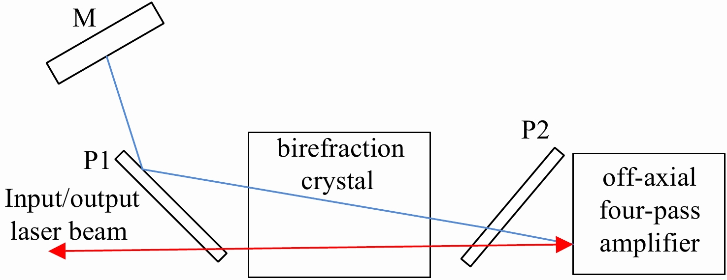
Literally, the off-axial eight-pass laser amplifiers developed from traditional off-axial four-pass amplifier via polarization control[
![]()
Figure 1.Basic mechanism of off-axis eight-pass laser amplifier
Consider the demand for alignment on the complex multi-pass optical system and the optical formation on the premise, we design an appropriate alignment configuration in the specific light path. In this alignment system, we adopt a couple of translatable concave lens installed with translation platform as the alignment lens (AL) for expanding alignment beam so as to illuminate full 4 pinholes in spatial filter 1, then Charged Coupled Device (CCD) cameras (resolution 1280×1024, pixel size 4.8 μm×4.8 μm, operation wavelength 1053 nm) can obtain pinhole imaging pictures of both sides via image lens (IL), at this point, target surface of the CCD gain leak light of the beam with a very low energy of 300−400 nJ. On the one hand from CCD1 we can get 1st, 3rd, 5th, 7th pass pinhole image with AL1 (f =−350 mm) and IL1 (f =160 mm) in the path, on the other hand from CCD2 we can get 2nd, 4th, 6th, 8th pass pinhole image with AL2 (f =−200 mm) and IL2 (f =160 mm) in the path, Fig. 2 shows the laser path.
![]()
Figure 2.Off-axis eight-pass laser path
Initially, CCDs obtain pinhole image, then the upper computer acquires and analyzes marginal pixel data to confirm centre point of pinhole as reference. It is worth mentioning that our alignment progress should be implemented pass-by-pass. There is no longer need for the alignment lens so we move them out of the path in advance. 1st pass corresponds to M34-A reflector frame, 2nd pass corresponds to M0-1 reflector frame, 3rd pass corresponds to M0-2 frame, 4th pass will get alignment once 3rd pass gets alignment since it is conjugate, 5th pass corresponds to M0-3, all of 6th, 7th, 8th pass are conjugate therefore once 5th pass gets alignment successfully, so do they. In case laser beam alignment should be implemented pass-by-pass, we equally divide the reference into four squared parts, which means 8 parts in sum. Fig.3 illustrates the reference design.
![]()
Figure 3.Alignment reference design
Have reference prepared in specific software, we utilize CCDs to collect beam spot information of the laser beam via lens for expanding. At this point, we prefer using ant colony algorithm[
![]()
Figure 4.Progress of edge detection
In order to correct beam pointing error, it is essential to adjust reflector frames refer to error data. For the sake of controlling reflector frames, we configure 64-subdivision step motor on each frame we need to adjust, as well as Beckhoff programmable logic controller (PLC) CX2030 to control motor drive EL7041-0052 via EtherCAT network EK1100. In this part the correspondence between pixel and motor step must be precisely clear to achieve accuracy of the alignment, due to our previous work, the one step resolution of motors is 3.6″(18 μrad). According to pixel size of CCDs and image focal distance, we could figure out the correspondence between motor movement of one step and image movement of pixel size via Eq(1). Therefore we could realize a fairly accurate motor control in terms of position error.
M is the amount movement of pixel size when the motor moves one step, F is the image focal distance and A is one square pixel length. Approximately we define the correspondence between motor step and pixel movement is 6:1, which means 6 absolutely vertical nor horizontal steps movement of the motor represents one pixel movement of the image.
We integrally develop procedures by QT development tool via C++ shown as Fig.5. Hence a closed loop automated alignment system is effectively achieved.
![]()
Figure 5.Closed loop automated alignment system
The software user interface provides function buttons consists of launcher, mode configuration, progress check, and operation daily record, etc. Additionally, it demonstrates real time beam pointing by CCD, monitors the whole progress of alignment demonstrated as Fig.6.
![]()
Figure 6.Alignment progress
2 Experimental results & evaluations
In the initial experimental section, we acquire pinhole image, then we are able to establish spot reference by figuring out the centre of circular area with high gray scale pixels, shown as Fig.7.
![]()
Figure 7.Alignment reference installation
With the usage of interdisciplinary knowledge which can be appreciated as a union of mechanics, optics, electronics and programming, we appropriately give a brand new alignment method for off-axis eight-pass laser amplifier. Through this method, we acquire the far-field laser spot of eight passes under automated alignment, shown as Fig.8.
![]()
Figure 8.Far-field beam pointing progress
In addition, with the usage of CCD we can monitor the state of beam alignment in real time. The beam alignment would be kept or adjusted if error occurred at all time by the adoption of the automated alignment system. Furthermore, this software could also be integrated into upper control software for the whole amplifier system. Since this control system has started operating in off-axis eight-pass laser amplifier, its efficiency, accuracy as well as reliability are going to be examined.
During period of amplifier manufacture, the primal adjustment method of beam alignment on the amplifier used to be manipulating rotating shaft of the reflector frame manually, and at the very beginning it approximately takes half an hour to collimate all eight passes in the amplifier, then as we become proficient, this method still takes about twenty minutes. At present, we adopt automatic control and it takes approximately 5 min to reach beam alignment. The time cost on alignment is acquired by procedure management function we programmed in the software, which illustrates automated alignment system is more efficient than manual alignment, hence contributes to satisfy the massive demand for production capacity in large laser facility.
Besides, we prefer referring to the output laser beam quality in order to evaluate the achievement of the alignment. Considered that the fault tolerance on adjustment is inevitable in the experiment, the alignment system is expected to reach an accuracy of 30 μrad with the considerate limitation on pixel size and one step resolution of the step motor. Furthermore, the experimental near-field beam quality shown as below. It can be evaluated that the amplifier could output excellent laser beam quality via the automated alignment technique, demonstrated as Fig.9.
![]()
Figure 9.Near-field laser beam quality
As to assess the reliability of the automated alignment on the amplifier, we are going to leave a proper time for system operation so as to make a valid assessment on reliability.
3 Conclusion
The automated alignment technique including optics, mechanics, electronics and communication perfectly corresponds to off-axis eight-pass amplifier which contains a wide range of factors and achieves a fairly efficient and accurate performance. Additionally, it configures actual time overall progress monitor resulting in good reliability.
Interdisciplinary application seems to be a significant way to improve the performance of the amplifier. The alignment system design is only a section for optimizing the performance of off-axis eight-pass laser amplifier. In fact, there are massive prospective jobs to accomplish. We plan to apply artificial intelligence technique in laser amplifier system. For instance, it is fairly considered useful to adopt near-field image recognition and deep learning used in spectral compensation, which might lead to a great improvement on efficiency of the alignment system.
References
[1] Mason P, Divoký M, Ertel K, et al. Kilowatt average power 100 J-level diode pumped solid state laser[J]. Optica, 4, 438-439(2017).
[2] Zeng Xiaoming, Zhou Kainan, Zuo Yanlei, et al. Multi-petawatt laser facility fully based on optical parametric chirped-pulse amplification[J]. Optics Letters, 42, 2014-2017(2017).
[3] Boehly T R, Brown D L, Craxton R S, et al. Initial performance results of the OMEGA laser system[J]. Optics Communications, 133, 495-506(1997).
[4] Norman M J, Andrew J E, Bett T H, et al. Multipass reconfiguration of the HELEN Nd: glass laser at the atomic weapons establishment[J]. Applied Optics, 41, 3497-3505(2002).
[5] Koechner W. Solidstate laser engineering[M]. 4th ed. Berlin: Springer, 1996.
[6] Bowers M, Burkhart S, Cohen S, et al. The injection laser system on the National Ignition Facility[C]Proceedings of SPIE 6451, Solid State Lasers XVI: Technology Devices. 2006: 64511M.
[7] Spaeth M L, Manes K P, Kalantar D H, et al. Description of the NIF laser[J]. Fusion Science and Technology, 69, 25-145(2016).
[8] Wang Chao, Wei Hui, Wang Jiangfeng, et al. 1 J, 1 Hz lamp-pumped high-gain Nd: phosphate glass laser amplifier[J]. Chinese Optics Letters, 15, 011401(2017).
[9] Yao Ke, Gao Song, Tang Jun, et al. Off-axis eight-pass neodymium glass laser amplifier with high efficiency and excellent energy stability[J]. Applied Optics, 57, 8727-8732(2018).
[10] Yao Ke, Xie Xudong, Tang Jun, et al. An efficient off-axis multi-pass Nd: glass amplifier utilizing a birefringence crystal[J]. Laser Physics, 29, 115002(2019).
[11] Zacharias R A, Beer N R, Bliss E S, et al. Alignment and wavefront control systems of the National Ignition Facility[J]. Optical Engineering, 43, 2873-2884(2004).
[12] Ye Chengliang, Shang Jianhua, He Yan. Study of laser beam autocollimation system[J]. Laser & Optoelectronics Progress, 54, 051201(2017).
[13] Wang Shenzhen, Yuan Qiang, Zeng Fa, et al. Beam alignment based on two-dimensional power spectral density of a near-field image[J]. Optics Express, 25, 26591-26599(2017).
[14] Burkhart S C, Bliss E, Di Nicola P, et al. National Ignition Facility system alignment[J]. Applied Optics, 50, 1136-1157(2011).
[15] Wen Wenbo, Du Wei. An abstract on the ant colony algorithms[J]. Automation in Petro-chemical Industry, 19-21(2002).
[16] Liu Wen, Bie Hongxia. Colony optimization algorithm on noisy image edge detection[J]. Software, 34, 256-259(2013).


Set citation alerts for the article
Please enter your email address

© Copyright 2018-2021 | Chinese Laser Press. All Rights Reserved 沪ICP备15018463号-20