We design a plano-convex lens working in the terahertz (THz) frequency range and fabricate it using three-dimensional (3D) printing technology. A 3D field scanner is used to measure its focal properties, and the results agree well with the numerical simulations. The refractive index and absorption coefficient measurements via THz time-domain spectroscopy (THz-TDS) reveal that the lens material is highly transparent at THz frequencies. It is expected that this inexpensive and rapid 3D printing technology holds promise for making various THz optical elements.
Terahertz (THz) radiations are electromagnetic waves that are located in the frequency range of 0.1–10 THz. Due to their nonionizing properties, THz waves have been applied to security scanning, and to noninvasive testing, sensing, and communication[1–5]. To extend the applications of THz technology, optical devices working in the THz regime to manipulate THz waves, such as wave plates, splitters, lenses, and waveguides, are in great demand[6,7]. Among all these components, the lenses can focus and collimate the THz beam, serving as the basic optical element in THz imaging systems.
Ordinary glasses commonly used at optical frequencies are useless for THz applications, owing to their high extrinsic dielectric losses in the THz range. Fortunately, polymers show excellent transparency in the THz regime. Typical polymers, such as polymethylpentene, high-density polyethylene, and tsurupika, have been widely used to commercially fabricate THz lenses and windows[8–11]. Recently, a great amount of research efforts have been made to seek easily accessible materials suitable for THz applications. Siemion et al. demonstrated the aberration-correction diffractive paper lens for low-frequency THz radiation[12]. Han et al. suggested the possibility of using natural stones as THz components[13]. Unlike traditional refractive bulk devices, which achieve phase delays as light propagates through the thickness of the material, novel flat lenses can create an abrupt phase shift of the optical resonators right at the surface of the lenses[14–16]. Recently, an ultrathin THz planar lens has been reported, but low energy conversion efficiency has restricted its practical applications[17]. Recent advances in artificially engineered metamaterials, which show resonance properties in the THz frequency, make it possible to fabricate functional THz devices, such as filters and tubes[18,19].
As we know, commercial lenses are generally polished via computer numerical control machining, which is complicated and time consuming. In recent years, three-dimensional (3D) printing came to the foreground as a very competitive process in terms of cost and speed. Many works have reported on the applications of 3D printed THz devices, including waveguides, woodpile structures, and computer-generated volume holograms[7,20,21]. In our earlier work, 3D printing technology was employed to make spiral phase plates to generate a THz vortex beam[22,23].
Sign up for Chinese Optics Letters TOC. Get the latest issue of Chinese Optics Letters delivered right to you!Sign up now
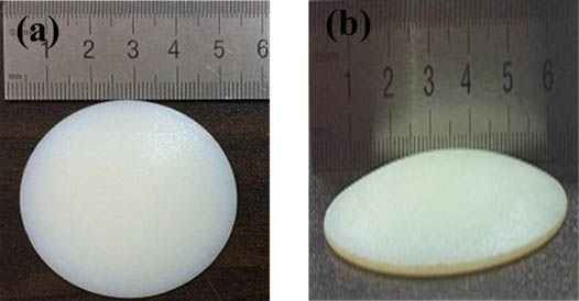
In this Letter, we design, fabricate, and characterize a plano-convex THz lens (Fig. 1). The THz time-domain spectroscopy (THz-TDS) measurement method is used to determine the optical characteristics of the lens material. It should be noted that this printing material is highly transparent in the THz regime, indicating that it is an ideal material to compose THz components. The design of the lens is implemented using the lens maker’s formula, and is assisted by the optical design software ZEMAX[24]. The focusing performance of this lens is characterized with a THz point scanning system. Experimental measurements coincide with the finite difference time-domain (FDTD) simulations. Moreover, this 3D printing technology is promising for fabricating various complex THz lenses, even a microlens array to control the illuminated areas[25].
Figure 1.(a) Top view of the printed lens. (b) Side view of the printed lens.
The composition material of the printed lens is the basic polymer ink “FullCure835 VeroWhite”[26]. We determine its optical properties by performing THz-TDS testing on a 6 mm thick slab made of this material[8,9,27]. The transmitted temporal THz waveforms with and without the slab are separately recorded as sample and reference signals, respectively. After the Fourier transform of these temporal data has been obtained, the refractive index and absorption coefficient of the polymer are achieved, as shown in Fig. 2. The absorption coefficient is rather low in the THz regime, about at 300 GHz. The refractive index increases slowly within the 0.1–0.6 THz spectral range, and it is about 1.655 at 300 GHz.
Figure 2.Characterizations of the polymer “FullCure835 VeroWhite.” The black curve is the refractive index, and the blue curve is the absorption coefficient.
According to the lens maker’s formula in geometry optics[28], when a collimated incident wave is assumed, the focal length of the lens is given by where , , and indicate the focal length, the curvature radius, and the refractive index of the lens, respectively. Figure 3 shows the ray-tracing diagram for the lens. We design the lens to have a thickness of 6.45 mm and a diameter of 50.8 mm, as shown in Fig. 3. With the curvature radius of and the refractive index of , according to Eq. (1) the theoretical focal length of the designed lens is about . The design is further verified with ZEMAX simulations[24].
Figure 3.Diagram of a lens illuminated by a Gaussian beam. , curvature radius; , radius of the lens; , thickness; , focal length.
Subsequently, we performed the lens fabrication process using a commercial Objet30 3D printer[26]. The structure files of the lens designed with the Pro/ENGINEER are exported in the STL file format and imported into the printer. The 3D geometry is converted into several slices. As each slice arrives, a set of print heads jets a layer of 28 μm thickness onto the build tray, which is then lowered by 28 μm to allow the deposition of the next slice. The printer employs two basic types of polymer: model and support. Model polymer acts as the structure material, while support polymer (“FullCure705”) normally acts as a base. After the entire print process is finished, only the model material remains in the designed 3D shape, while a high-pressure water jet washes the support material away. It is worthwhile to note that the surface morphology of the lens is not degraded after the water jet process, and that the structures’ surface smoothness is only determined by the printing precision. To our knowledge, the Objet30 3D printer has a resolution of 600 dpi (42 μm) in the and directions, and 900 dpi (28 μm) in the direction. As shown in Fig. 1, the fabricated plano-convex lens does not differ from the commercial THz lenses in vision. For our designed lens in this work, just 55 min and $8 are required. Our system costs less in both time and money compared to the traditional lens-making procedure.
Due to the rotational symmetry of the lens, the two-dimensional (2D) FDTD simulation is performed to evaluate the electromagnetic fields focused by the lens with the parameter values of previous designs. Perfectly matched layers are used at all boundaries. A 300 GHz Gaussian beam, linearly polarized in the direction and propagating along the direction, is added as the excitation source. The beam waist is located at , and the beam has a diameter of 20 mm. The flat surface of the lens is located at .
Figure 4(a) shows the beam profile (spatial 2D intensity distribution) of the Gaussian beam. As can be seen, the lens focuses the beam, and the minimum beam width is located at . To further investigate its focal properties, the on-axis intensity distribution behind the lens [cutting along the horizontal dotted line in Fig. 4(a)] is depicted in Fig. 4(b). The on-axis intensity increases gradually, reaches its maximum value, and then decreases as the propagation distance increases. The maximal axial intensity is located at . Since the main surface of the plano-convex lens is located at the spherical vertex (), it can be concluded that the focal length with the FDTD simulation is , close to the value of 97.7 mm obtained in the theoretical results. The radial intensity distribution of the focal spot is shown in Fig. 4(c) [cutting along the vertical dotted line in Fig. 4(a)]. The lateral intensity distribution of the focal spot accords with the Gaussian function, and the spot size is around 5 mm.
Figure 4.(a) 2D FDTD simulated intensity distribution of the focused Gaussian beam. (b) Axial normalized intensity distribution behind the printed lens [cutting along the red line in (a)]. (c) Lateral normalized intensity distribution [cutting along the green line in (a)].
A point-scanning test is conducted to measure the focal properties of the printed lens, with the experimental setup shown in Fig. 5. A 100 GHz Gunn diode (Spacek Labs model GW-102 P) coupled to a frequency tripler is used as the light source. It delivers a Gaussian beam at 300 GHz. The beam is collimated by a spherical lens, then directed to our 3D printed lens and focused behind the lens. The Schottky diode (Virginia Diodes, Inc.), mounted on a motorized translation stage, is employed to detect the intensity distribution of the THz beam behind the printed lens. An optical chopper at 300 Hz, which is connected to a lock-in amplifier (Stanford Research System SR-830), is used to reduce noise and extract a reliable signal.
The lateral intensity distribution is directly obtained through point scanning () on the plane. By varying the distance between the detector and the surface of the printed lens in steps of 12 mm over a range of 47–155 mm, ten specific positions along the direction are chosen. Finally, ten intensity profiles are measured.
The 2D profiles of the Gaussian beam at five different positions around the focus are shown in Fig. 6(a). It can be seen that the spot size along the propagation direction reaches its minimum value at two places, but at the distance of 95 mm, the spot energy is more concentrated. The normalized cross-section plot of the 2D profile at this minimum spot size is illustrated in Fig. 6(b). As can be seen from Fig. 6(b), the maximal intensity is not exactly at . We think this distortion probably comes from the slight misalignment between the center of the translation-stage-scanning range and the spot center, but it has no crucial influence on the scanned profile results. The radial intensity distribution shows a Gaussian-shaped profile, in accordance with Fig. 4(c). Then, we fit it with the Gaussian function and find the full width at half-maximum (FWHM) is about 3.5 mm. It is depicted as the red line in Fig. 6(b).
Figure 6.(a) 2D Gaussian beam intensity profile images obtained by the point-scanning method. (b) Curve fitting (the red line) of the measured radial intensity distribution at . (c) FWHM (the red line) and the axial maximal intensity distribution (the blue line) over the propagation distance.
Furthermore, with this Gaussian function fitting method, we analyze how the FWHM changes with the varying distance. The plot of the beam diameter as a function of the propagation distance is shown as the red curve in Fig. 6(c). We also analyze the axial intensity distribution. The maximal intensity values at each propagation distance are depicted as the blue line in Fig. 6(c). As can be seen, the Gaussian beam has the maximal intensity value as well as the minimal FWHM at the distance of 95 mm. These experimental results agree well with the expected results.
In conclusion, we demonstrate the design, fabrication, simulation, and experimental testing of a 3D printed THz lens. The printing material exhibits a low absorption coefficient and a stable refractive index over a broad frequency. Our measured focused beam profiles are well explained by the numerical simulation. This 3D printed lens has several obvious advantages: it is easily fabricated, effective over a broad THz frequency range, and compatible with more complicated geometries. It suggests that the 3D printing technology provides a new insight into THz optical elements.
[8] B. M. Fischer. Broadband THz time-domain spectroscopy of biomolecules: a comprehensive study of the dielectric properties of biomaterials in the far-infrared(2005).