Author Affiliations
1State Key Laboratory of Optoelectronic Materials and Technologies, School of Electronics and Information Technology, Sun Yat-sen University, Guangzhou 510006, China2State Key Laboratory of Optical Fiber and Cable Manufacture Technology, Yangtze Optical Fiber and Cable Joint Stock Limited Company, Wuhan 430073, China3Photonics Group, Merchant Venturers School of Engineering, University of Bristol, Bristol BS8 1UB, UK4e-mail: s.yu@bristol.ac.ukshow less
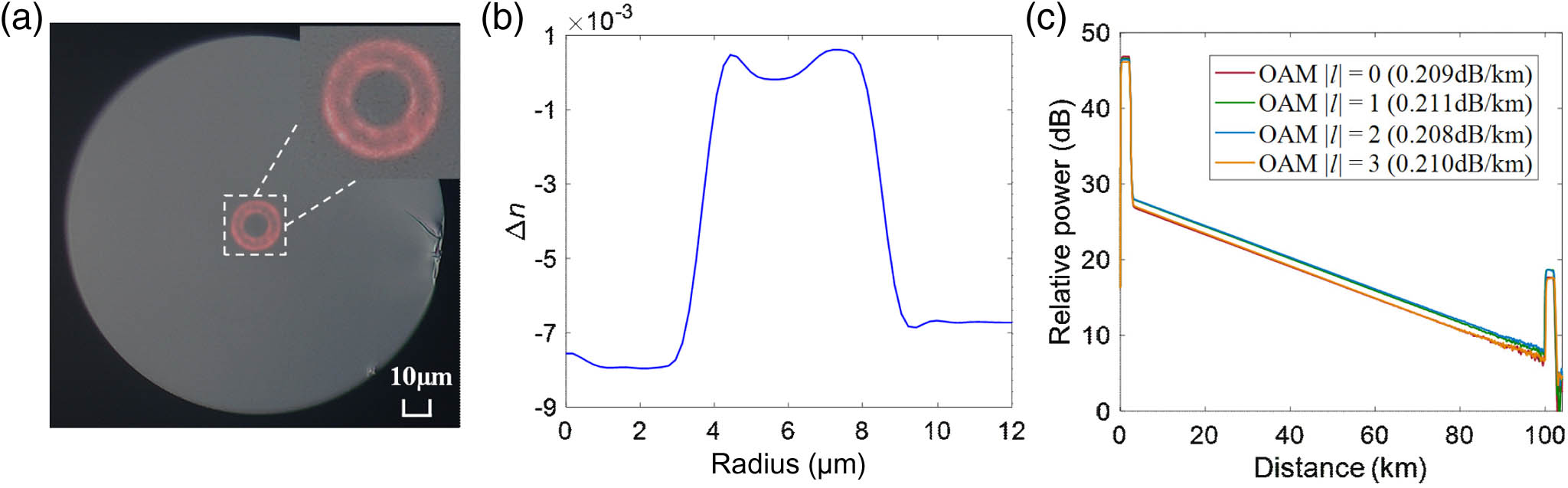
Fig. 1. (a) Cross-sectional diagram, (b) RIP, and (c) propagation loss of the RCF used in the experiment.
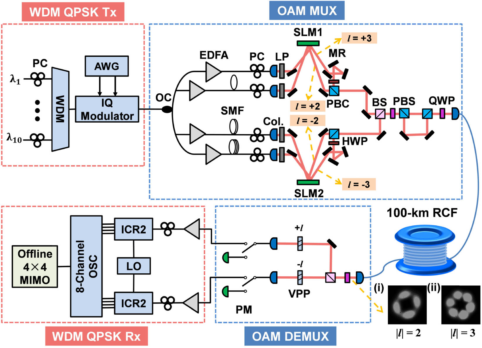
Fig. 2. Experimental setup for OAM-MDM/WDM data transmission. The intensity profiles of MGs (i) |l|=2 and (ii) |l|=3 after 100-km RCF transmission. WDM, wavelength-division multiplexer; AWG, arbitrary waveform generator; OC, optical coupler; EDFA, erbium-doped fiber amplifier; PC, polarization controller; Col., collimator; SMF, single-mode fiber; LP, linear polarizer; SLM, spatial light modulator; MR, mirror; PBC, polarizing beam combiner; HWP, half-wave plate; BS, beam splitter; QWP, quarter-wave plate; PBS, polarizing beam splitter; VPP, vortex phase plate; PM, power meter; ICR, integrated coherent receiver; LO, local oscillator. Note that the optical switches are utilized to switch between setups for fiber characterization and data transmission.
Fig. 3. The absolute values of complex tap weights of the 16 FIR filters in 4×4 MIMO equalizer to equalize the four modes in MGs (a) |l|=2 and (b) |l|=3 after 100-km RCF transmission.
Fig. 4. Measured BER versus OSNR of MGs (a) |l|=2 and (b) |l|=3 at 1550.12 nm after 100-km RCF transmission; constellation diagrams of the recovered 16-GBaud QPSK signals of all simultaneously transmitted OAM mode channels of MGs (c) |l|=2 and (d) |l|=3 at an OSNR of 24 dB after 100-km RCF transmission.
Fig. 5. (a) Measured BERs of all 80 channels after 100-km RCF transmission; (b) optical spectra of the 10 WDM channels at the transmitter side.
RCF Types | Loss (dB/km) | Signal and MIMO DSP | Number of MDM Channels | Number of WDM Channels | Capacity (Tbit/s) | Distance (km) | Capacity-Distance Product [(Tbit/s) · km] | Refs. | Elliptical ring core | — | QPSK, MIMO free | 6 | 1 | 0.384 | 0.9 | 0.3456 | [17,18] | Graded index | — | OOK, MIMO free | 2 | 1 | 0.02 | 0.1 | 0.002 | [19] | Step index | — | OOK, MIMO free | 2 | 1 | 0.02 | 1 | 0.02 | [20] | Graded index | — | OOK, MIMO free | 3 | 1 | 0.0375 | 0.36 | 0.0135 | [21] | Graded index | 0.75 | 16QAM/QPSK-DMT, MIMO free | 3 | 1 | 0.1 | 1 | 0.1 | [11] | Graded index | 0.75 | QPSK-DMT, MIMO free | 2 | 1 | 0.04 | 18.4 | 0.736 | [11] | Graded index | 1 | 8QAM, MIMO free | 2 | 112 | 8.4 | 18 | 151.2 | [22] | RIP-modulated | 0.31 | OOK, MIMO free | 2 | 1 | 0.015 | 50 | 0.75 | [23] | RIP-modulated | 0.21 | OOK, MIMO free | 2 | 4 | 0.12 | 100 | 12 | [24] | Step index | 0.3 | 16QAM, MIMO | 10 | 1 | 1.12 | 1 | 1.12 | [25] | Step index | 0.3 | QPSK, MIMO | 10 | 1 | 0.56 | 24 | 13.44 | [25] | Graded index | 1 | QPSK, MIMO | 8 | 10 | 5.12 | 10 | 51.2 | [12] | RIP-modulated | 0.31 | QPSK, MIMO | 8 | 10 | 2.56 | 50 | 128 | [26] | RIP-modulated | 0.21 | QPSK, MIMO | 8 | 10 | 2.56 | 100 | 256 | This work |
|
Table 1. Data Transmission of RCF-Based MDM Systems in Recent Works
| | | | | | () | 0.7 | 1.8 | 2.5 | Attenuation | (dB/km) | 0.209 | 0.211 | 0.208 | 0.210 | DGD | (ns/km) | 0 | 3.2 | 8.5 | 13.1 |
|
Table 2. Characteristics of the Fabricated RCF
| Input MG | Input MG | Output MG | Output MG | Output MG | Output MG | Crosstalk (dB) | 0 | −12.495 | −11.486 | 0 |
|
Table 3. Measured Inter-MG Crosstalk among the Two Used High-order OAM MGs over the 100-km RCF Transmission System