• Chinese Journal of Lasers
  • Vol. 50, Issue 24, 2402304 (2023)
Runsen Zhou1, Kaiwen Wei1、*, Jingjing Liang2, Jia Chen1, Gaohang Li1, Liang Qu1, Mengna Liu1, Xiangyou Li1, Xiaofeng Sun2, and Xiaoyan Zeng1
Author Affiliations
  • 1Wuhan National Laboratory for Optoelectronics, Huazhong University of Science and Technology, Wuhan 430074, Hubei , China
  • 2Institute of Metal Research, Chinese Academy of Sciences, Shenyang 110016, Liaoning ,China
  • show less
    DOI: 10.3788/CJL230662 Cite this Article Set citation alerts
    Runsen Zhou, Kaiwen Wei, Jingjing Liang, Jia Chen, Gaohang Li, Liang Qu, Mengna Liu, Xiangyou Li, Xiaofeng Sun, Xiaoyan Zeng. Basic Process of New Directional Solidification Nickel‑Based Superalloy Fabricated by Laser Powder Bed Fusion[J]. Chinese Journal of Lasers, 2023, 50(24): 2402304 Copy Citation Text show less
    Gas-atomized ZGH451 nickel-based superalloy powder. (a) Particle morphology; (b) particle size distribution
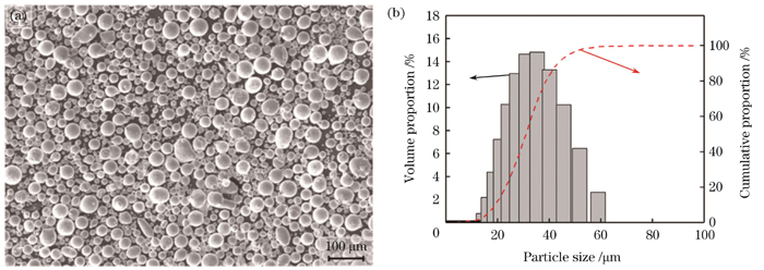
    Fig. 1. Gas-atomized ZGH451 nickel-based superalloy powder. (a) Particle morphology; (b) particle size distribution
    Forming ZGH451 nickel-based superalloy by LPBF. (a) Laser scanning strategy; (b) size of tensile specimen; (c) formed samples
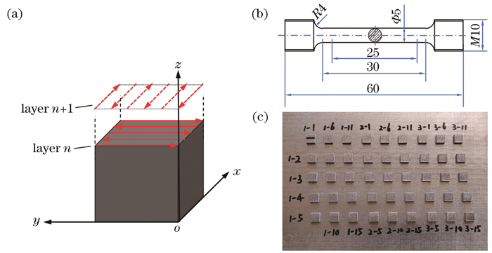
    Fig. 2. Forming ZGH451 nickel-based superalloy by LPBF. (a) Laser scanning strategy; (b) size of tensile specimen; (c) formed samples
    Variation curves of relative density of ZGH451 alloy formed by LPBF with scanning speed and scanning spacing under different laser powers. (a) 200 W; (b) 150 W
    Fig. 3. Variation curves of relative density of ZGH451 alloy formed by LPBF with scanning speed and scanning spacing under different laser powers. (a) 200 W; (b) 150 W
    Process window and metallurgical defect feature maps of typical samples at laser power of 200 W
    Fig. 4. Process window and metallurgical defect feature maps of typical samples at laser power of 200 W
    Process window and metallurgical defect feature maps of typical samples at laser power of 150 W
    Fig. 5. Process window and metallurgical defect feature maps of typical samples at laser power of 150 W
    Typical distribution characteristics of cracks in ZGH451 superalloy formed by LPBF. (a) SEM image; (b) local magnification of Fig. 6 (a); (c) EBSD grain orientation distribution; (d) grain angle difference on both sides of crack
    Fig. 6. Typical distribution characteristics of cracks in ZGH451 superalloy formed by LPBF. (a) SEM image; (b) local magnification of Fig. 6 (a); (c) EBSD grain orientation distribution; (d) grain angle difference on both sides of crack
    SEM images of typical samples of crack-free and high-density ZGH451 superalloy formed by LPBF. (a) Overall morphology of microstructure; (b) coarsened dendrites at bottom of molten track; (c) precipitates between dendrites; (d) different oriented dendrites at edge of molten track
    Fig. 7. SEM images of typical samples of crack-free and high-density ZGH451 superalloy formed by LPBF. (a) Overall morphology of microstructure; (b) coarsened dendrites at bottom of molten track; (c) precipitates between dendrites; (d) different oriented dendrites at edge of molten track
    Analysis of precipitated phase characteristics of crack-free and high-density ZGH451 superalloy samples formed by LPBF. (a) TEM dark field image; (b) EDX element surface distribution; (c) HR-TEM image and electron diffraction spot diagram
    Fig. 8. Analysis of precipitated phase characteristics of crack-free and high-density ZGH451 superalloy samples formed by LPBF. (a) TEM dark field image; (b) EDX element surface distribution; (c) HR-TEM image and electron diffraction spot diagram
    EBSD maps of crack-free and high-density ZGH451 superalloy samples formed by LPBF at different positions. (a) Inverse pole figure (IPF) of grain morphology and orientation characteristics at bottom; (b) IPF of grain morphology and orientation characteristics at middle; (c) IPF of grain morphology and orientation characteristics at top; (d) pole figure of {001} characteristic crystal plane at bottom; (e) pole figure of {001} characteristic crystal plane at middle; (f) pole figure of {001} characteristic crystal plane at top
    Fig. 9. EBSD maps of crack-free and high-density ZGH451 superalloy samples formed by LPBF at different positions. (a) Inverse pole figure (IPF) of grain morphology and orientation characteristics at bottom; (b) IPF of grain morphology and orientation characteristics at middle; (c) IPF of grain morphology and orientation characteristics at top; (d) pole figure of {001} characteristic crystal plane at bottom; (e) pole figure of {001} characteristic crystal plane at middle; (f) pole figure of {001} characteristic crystal plane at top
    SEM images of tensile fractures of crack-free and high-density ZGH451 formed by LPBF
    Fig. 10. SEM images of tensile fractures of crack-free and high-density ZGH451 formed by LPBF
    ElementNiCrCoWAl+Ti+TaMoHfCB
    ValueBal.8.0008.0008.00012.2002.0001.5000.1000.015
    Table 1. Nominal chemical compositions of ZGH451 nickel-based superalloy (mass fraction, %)
    ParameterValue
    Laser power /W150, 200
    Scanning velocity /(mm/s)600, 800, 1000, 1200, 1400, 1600
    Hatch spacing /mm0.06, 0.08, 0.10, 0.12
    Layer thickness /mm0.02
    Phase angle /(°)90
    Table 2. Parameters for LPBF experiment
    SampleYS/MPa
    ZGH451979.5±31.0
    DD91017
    DD6930
    CMSX-4917
    Table 3. Comparison of yield strength between ZGH451 formed by LPBF superalloy and other single crystal superalloys[35-36]
    Runsen Zhou, Kaiwen Wei, Jingjing Liang, Jia Chen, Gaohang Li, Liang Qu, Mengna Liu, Xiangyou Li, Xiaofeng Sun, Xiaoyan Zeng. Basic Process of New Directional Solidification Nickel‑Based Superalloy Fabricated by Laser Powder Bed Fusion[J]. Chinese Journal of Lasers, 2023, 50(24): 2402304
    Download Citation