• High Power Laser and Particle Beams
  • Vol. 34, Issue 10, 104010 (2022)
Yingchao Du1, Han Chen1, Hongze Zhang1, Qiang Gao1, Qili Tian1, Zhijun Chi2, Zhi Zhang1, Hao Zha1, Jiaru Shi1, Lixin Yan1, Rui Qiu1, Cheng Cheng1, Taibin Du1, Renkai Li1, Huaibi Chen1, Wenhui Huang1, and Chuanxiang Tang1、*
Author Affiliations
  • 1Department of Engineering Physics, Tsinghua University, Beijing 100084, China
  • 2College of Nuclear Science and Technology, Beijing Normal University, Beijing 100875, China
  • show less
    DOI: 10.11884/HPLPB202234.220132 Cite this Article
    Yingchao Du, Han Chen, Hongze Zhang, Qiang Gao, Qili Tian, Zhijun Chi, Zhi Zhang, Hao Zha, Jiaru Shi, Lixin Yan, Rui Qiu, Cheng Cheng, Taibin Du, Renkai Li, Huaibi Chen, Wenhui Huang, Chuanxiang Tang. A very compact inverse Compton scattering gamma-ray source[J]. High Power Laser and Particle Beams, 2022, 34(10): 104010 Copy Citation Text show less
    Schematic diagram of the very compact inverse Compton scattering gamma-ray source (VIGAS)
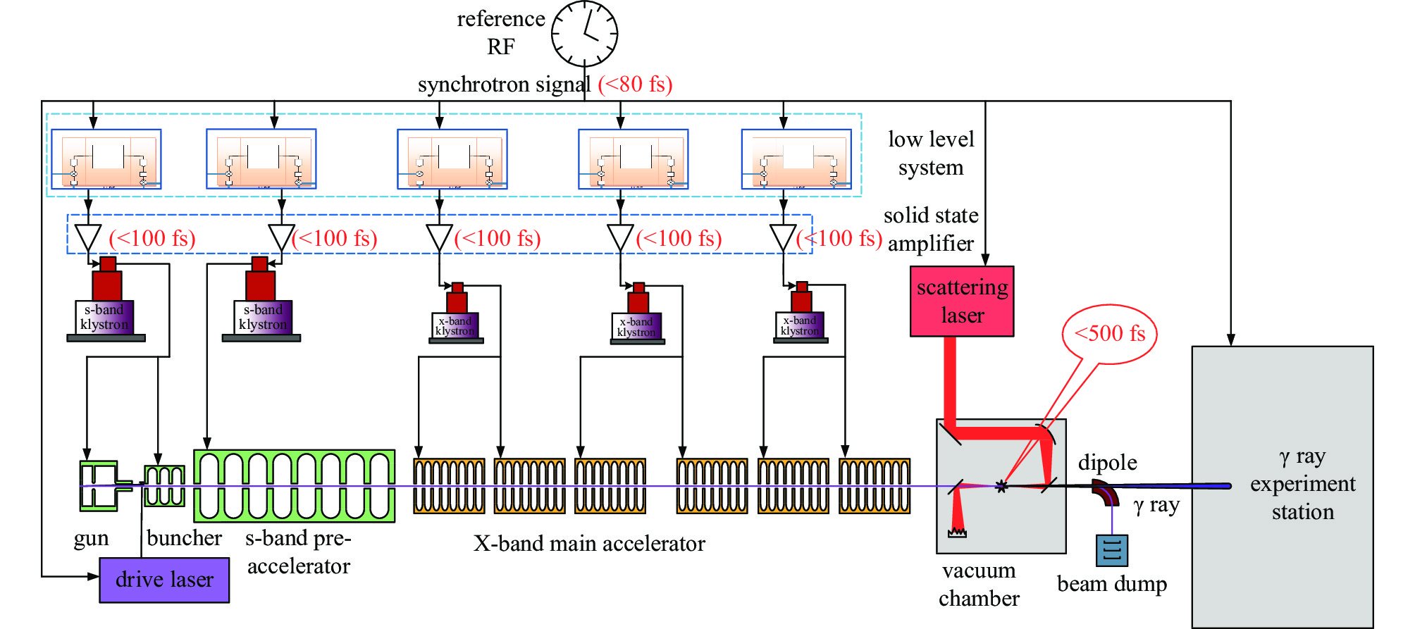
    Fig. 1. Schematic diagram of the very compact inverse Compton scattering gamma-ray source (VIGAS)
    Layout of the accelerator in VIGAS
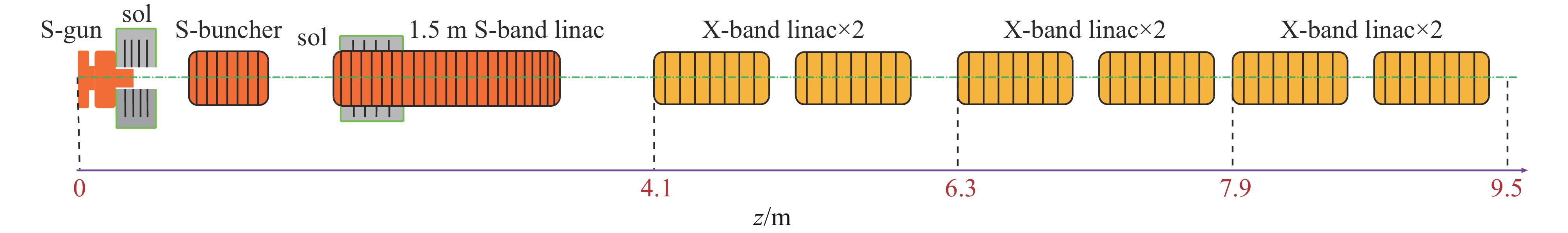
    Fig. 2. Layout of the accelerator in VIGAS
    Relation between bunch length and emittance plus energy spread after optimization
    Fig. 3. Relation between bunch length and emittance plus energy spread after optimization
    Pareto front of emittance and bunch length with 200 pC bunch charge and 500 pC bunch charge
    Fig. 4. Pareto front of emittance and bunch length with 200 pC bunch charge and 500 pC bunch charge
    Beam dynamics simulation results in the case of 200 pC bunch charge
    Fig. 5. Beam dynamics simulation results in the case of 200 pC bunch charge
    Bunch energy and emittance versus the ratio of acceleration gradient
    Fig. 6. Bunch energy and emittance versus the ratio of acceleration gradient
    Photon energy versus the ratio of acceleration gradient
    Fig. 7. Photon energy versus the ratio of acceleration gradient
    Block diagram of driving laser shaping design
    Fig. 8. Block diagram of driving laser shaping design
    Block diagram of scattering laser design
    Fig. 9. Block diagram of scattering laser design
    Simulated photon yield at different photon energy
    Fig. 10. Simulated photon yield at different photon energy
    Photon bandwidth and the proportion within the collection angle versus the collection angle
    Fig. 11. Photon bandwidth and the proportion within the collection angle versus the collection angle
    Photon spectroscopy within different collection angles using 800 nm scattering laser
    Fig. 12. Photon spectroscopy within different collection angles using 800 nm scattering laser
    Photon spectroscopy within different collection angles using 400 nm scattering laser
    Fig. 13. Photon spectroscopy within different collection angles using 400 nm scattering laser
    Photon spectroscopy in simulation taking jitter into consideration
    Fig. 14. Photon spectroscopy in simulation taking jitter into consideration
    parametervalue
    γ ray photon energycontinuously adjustable between 0.2~4.8 MeV
    relative bandwidth (RMS)/%<1.5 (after collimation)
    photon yield/(photons·s−1) >4.0×10⁸@0.2~2.4 MeV;>1.0×10⁸@2.4~4.8 MeV
    photon yield within 1.5% bandwidth>4.0×10⁶@0.2~2.4 MeV; >1.0×10⁶@2.4~4.8 MeV
    degree of polarizationadjustable from linear to circular polarization
    Table 1. Performance parameters of VIGAS
    parametervalue
    bunch energy/MeV50~350
    bunch charge/pC>200
    normalized emittance/(mm·mrad)<0.6
    bunch length/ps<2
    energy spread/%<0.3
    focused spot size/µm<20
    repetition rate/Hz10
    Table 2. Parameters of electron beam in VIGAS
    parametervalue
    800 nm400 nm
    bandwidth/nm<15<8
    pulse energy/J>1.5>0.8
    pulse length (FWHM)/ps<10
    focused spot size (RMS)/μm<10
    Table 3. Parameters of scattering laser in VIGAS
    parametersrangeoptimization result
    200 pC500 pC
    laser duration/ps[4, 20]7.277.09
    laser beam size (RMS)/mm[0.2, 2]0.20.33
    launch phase/(°)[−20, 20]5.43.0
    gun solenoid strength/T[0.15, 0.35]0.20240.2018
    gun solenoid center/m[0.213 7, 0.213 7]0.21370.2137
    buncher field strength/(MV·m−1) [20, 50]36.143.4
    buncher center/m[0.73, 0.9]0.96650.9665
    buncher phase/(°)[−110, −80]−100−98.5
    linac center/m[1.5, 2]2.4022.402
    linac solenoid center/m[1.5, 2]1.61.6
    linac solenoid strength/T[0, 0.2]0.08040.109
    Table 4. Variable parameters in the optimization
    normalized emittance/(μm·rad)bunch length (RMS)/mmbunch energy/MeVenergy spread (RMS)/MeVbunch charge/pC
    0.2940.208361.30.45200
    0.6230.202361.50.40500
    Table 5. Optimized beam parameters with 200 pC bunch charge and 500 pC bunch charge
    parametersvalue
    central wavelength/nm267
    repetition rate/Hz10
    pulse energy/μJ2~500
    pulse width (FWHM)/ps5-10
    rising and falling edge (10%~90%)/ps1.0
    beam size (RMS)/mm0.2~2
    energy jitter (RMS)/%<2.0
    time jitter between RF and laser (RMS)/ps<0.1
    Table 6. Parameters of the driving laser system
    parametersjitter range
    bunch charge/%$ \pm 2 $
    laser duration/%$ \pm 2 $
    laser beam size/%$ \pm 2 $
    gun field strength/%$ \pm 0.1 $
    gun phase$ \pm 0.5 $
    buncher field strength/%$ \pm 0.1 $
    buncher phase$ \pm 0.5 $
    S band linac field strength/%$ \pm 0.1$
    S band linac phase$ \pm 0.5 $
    X band linac field strength/%$ \pm 0.1 $
    X band linac phase$ \pm 1 $
    scattering laser pulse energy/%$ \pm 2$
    relative position between electron and laser beam/μm$ \pm 3 $
    arrival time/ps$ \pm 0.25 $
    Table 7. Parameter jitter range in the joint parameter sweep
    Yingchao Du, Han Chen, Hongze Zhang, Qiang Gao, Qili Tian, Zhijun Chi, Zhi Zhang, Hao Zha, Jiaru Shi, Lixin Yan, Rui Qiu, Cheng Cheng, Taibin Du, Renkai Li, Huaibi Chen, Wenhui Huang, Chuanxiang Tang. A very compact inverse Compton scattering gamma-ray source[J]. High Power Laser and Particle Beams, 2022, 34(10): 104010
    Download Citation